
Owner's Manual

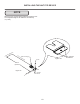


Cabinet
"Z" bracket
3
4" black
screws
(3 places)
Figure 28
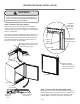
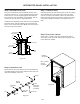
Step 7: Install the door
Carefully open the top and bottom hinges on the door being
careful as there are many pinch points. Place the hinges
over the 4 screws in the cabinet, 2 at the top and 2 at the
bottom and slide the door into position. Tighten the 4 hinge
screws with a phillips screwdriver. (See Figures 25 and
25a).
SECTION A-A
SCALE 1 : 1
LOCK
NUT
BRASS EXTENSION
CAM
PHILLIPS SCREW
13/16 COUNTER
BORE 7/16 DEEP
1/2 HOLE
3/4 INCH
WOOD PANEL
SPRING WASHER
INNER
DOOR
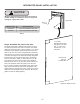
Step 8: Secure the cabinet
3
4" black screws from the literature pack to
secure the counter top to the cabinet top through the holes
in the cabinet "Z" bracket.
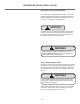
INTEGRATED PANEL INSTALLATION
Figure 27
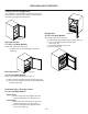
Step 6: Install lock cam
Attach the lock cam to the back of the lock assembly with
the phillips head screw provided. Orient the lock cam verti-
cally when installing on the lock.
Cam stop
washer
Spring
washer
Cam
Set screw
Lock
Key
Retainer
nut
Screw
Brass
(2 lengths
provided)
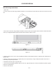
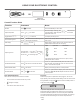
Step 5: Assemble lock parts
3
4" thick integrated panels and the
shorter one for
5
8" thick integrated panels. Assemble the
screw to the lock as shown in Figure 26 and 27.
Install this lock assembly into the lock hole in the integrated
panel and secure with the retaining nut on the back side
with a 15 mm socket and ratchet. Make sure the key slot in
the front of the lock is vertical.
Figure 26
18