Marvelmind Indoor Navigation System Operating manual v2018_09_04 www.marvelmind.
Table of contents 1. Version changes ...................................................................................................................................... 4 2. Executive summary.................................................................................................................................. 5 3. Basics of the system ................................................................................................................................ 7 3.1 What’s in the box .......
8.1 Beacon HW v4.9 external interface 4x4 pinout top view ............................................................... 81 8.2 Modem HW v4.9 external interface pinout top view ...................................................................... 82 9. Advanced system settings and optimization .......................................................................................... 83 9.1 How to place beacons ...........................................................................................
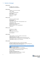
1. Version changes V2018_08_30 - New SW features descriptions New Dashboard view descriptions V2018_08_03 - Calibration of accelerometer added F.A.Q.
- Settings to get correction north direction 2. Executive summary Marvelmind Indoor Navigation System is an off-the-shelf indoor navigation system, designed to provide precise (±2cm) location data to autonomous robots, vehicles (AGV), and copters. It can also be used to track moving objects via mobile beacons attached to them. Other applications include, for example, forklifts, virtual reality (VR) systems, helmets for construction workers or miners, etc.
Key capabilities: Parameter Distance between beacons Coverage area Location precision Location update rate Technical Specifications - Reaches up to 50 meters in lab conditions.
3. Basics of the system 3.1 What’s in the box Starter Set: - 4 x Stationary beacons 1 x Mobile beacon (aka “hedgehog”) 1 x Modem/Router * Starter set includes beacons without IMU. All pictures shown are for illustration purposes only. Actual product may vary due to product enhancement. Characteristics are the same or better unless stated otherwise.
3.2 Indoor Navigation System architecture Marvelmind Indoor Navigation System provides high-precision (±2cm) indoor coordinates for autonomous robots and systems (“indoor GPS”). A brief description of the key elements of the system is given on the scheme below.
3.
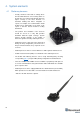
4. System elements 4.1 Stationary beacons - Usually, mounted on the walls or ceilings above the robot with ultrasonic sensors facing down—to provide the most robust unobstructed ultrasonic signal coverage to the robot.
4.2 Mobile beacon (“hedgehog”) - 11 - The mobile and stationary beacons can be easily interchanged by selecting the option in the Dashboard - The mobile beacons designed to be placed on a robotic vehicle, copter/drone, AGV, or helmet to trace its location. Formally speaking, location of the mobile beacon is traced—not the robot itself.
4.
4.4 13 Modem/router - Modem is the central controller of the system. It must be powered at all time when the Navigation System is working. It recommended to use an active USB hub for that purpose or even a regular cellular phone USB power supply.
4.5 Charging beacons and other details - The Beacon has 5 sensors (transducers): RX1, RX2, RX3, RX4, and RX5 - Charging occurs automatically every time a USB charger is attached to the board. LED 1 is active and lights red - It takes 1–2 hours to fully charge the board’s battery - If you plan to use a charger for permanent powering of the beacon, make sure that the power source is not noisy (The USB +5V is not noisy). The performance can be monitored by using: Dashboard => View => Oscilloscope.
4.6 DIP switch modes 1) Power = OFF, DFU = OFF: Charging is possible; beacon disconnected from internal battery. This mode recommended, if you want to keep the battery fully charged for a long time and to store the beacon on the shelf 2) Power = ON, DFU = OFF (pictured below): Normal working mode for the beacon. The beacon is fully powered and will wake up every a few seconds to monitor radio signals from the modem.
5. Setting up the system 5.1 First setup of your device The steps below describe the very first time you set up of the system: 16 - Unpack the system. Watch the help video: https://youtu.be/sOce7B2_6Sk - Check that your boards are charged; see that all switches on the beacons are in the correct position (Power = ON; DFU = OFF). See the paragraph DIP switch modes - Press the RESET button on each beacon. If LED 2 is not blinking, it means your board is turned off or discharged.
5.2 HEX programming - After charging boards, download the latest stable SW package from https://marvelmind.com/pics/marvelmind_SW.zip - Run the Dashboard and update the SW for all beacons and modem using Dashboard => Firmware => Choose the file => Program - If you see the message “Not found modem connection to computer through USB” in the Dashboard or your PC does not recognize beacons/modem, it usually means that the STM32 driver is not installed.
5.3 DFU Programming DFU programming or SW uploading is used when HEX SW uploading in the Dashboard cannot be used.
- - After a couple of seconds, the DFU will be uploaded to the beacon. Make sure it actually takes 1–3 seconds and does not happen immediately. Otherwise, the SW has not been really uploaded. If the DFU appears to upload immediately, check the "Choose" button you used or change the version of DfuSe SW you selected - Move the DIP switch into Power = ON, DFU = OFF - Start the Dashboard and press the RESET button on the beacon - Check SW on the beacon afterwards - Everything should be OK with SW now.
5.
- The system may run the frequency search, if it is the very first time you are waking up the beacons. If this step does not work, disconnect the modem and connect that beacon again via USB. Press the DEFAULT button in the Dashboard and the Read All button to make sure that the radio settings are really the default ones - Compare the radio settings on the modem and the radio settings on the beacon.
measured at all. Try to re-position them because usually there is an obstruction of some sort in the between the beacons. It also may be different height of beacons’ positon. Reset all these beacons. 22 - Use View => Table of distances to monitor the measured distances between beacons - Freeze the map by clicking the button.
- 23 In the dashboard, you can upload a picture / map of your room. You can use different picture for every floor.
6. Dashboard menu and parameters 6.
6.2 Table of distances Table of distances shows measured distance between all the beacons. The map and its graphical visualization depends on distances. So, that is very important part of the system. There are two ways of measuring: 1) Measuring by ultrasound (automatic) 2) Measuring by user (manual) *In noisy cases and cases with a long distance it is better to use manual input 1) Measuring by ultrasound: - In most cases, the system builds the table of distances automatically.
Step 3. Now, cells are frozen. That values would not change until you unfreeze it. Even if beacons had been moved, distance would stay. Be careful with frozen cells because a small mistake can cause a huge impact on your tracking Step 4. Repeat for all cells - White means that everything is good, you can freeze the map - Yellow means that something seems to be wrong, check distances and sensors before freezing - Red means some critical misses, DO NOT freeze the map.
6.3 Devices list Devices list contains information about all the beacons in the system. It also allows to search, add and delete it.
6.
6.5 Map settings Map settings helps to work with the map. Can do following things: 29 - Save map – saves map as .ini file into Dashboard folder/maps - Load map – loads map from .
6.6 Modem/beacon’s quick control panel Control panel allows user to interact with devices. It can work with one device, or with all devices in the system.
6.7 Modem’s settings This bar allows user to adjust devices very precisely. It contains a lot of parameters for advanced usage Modem’s settings Unique processor ID for each device (beacon or modem) Location update rate settings: 1/20Hz – 16Hz+. Notice that real update rate may be limited by distances between beacons or radio profile TBD Internal filter. More – faster objects can be tracked. Less – better filtering against location jumps Set of power saving features.
TBD Power supply voltage of the device 5V+-0.2V is OK N/A Time from the latest reset Measured temperature of the processor’s crystal Strength of the radio signal from modem to beacons and vice versa. Maintain in the range of -25dBm to -80..90dBm. Higher value - may overload. Lower – lost packets Chosen working band Exact working frequency Logical address of the device. Keep 2..255 for beacons.
Advanced settings TBD Enabling will allow direction along with location: TBD TBD TBD 33
Parameters of radio Real carrier frequency Selected radio profile with a set of profile settings. Choose between 38kbps (better range and interference immunity, but slower); 153kbps – balanced; and 500kbps – the fastest, but the lowest radio range and least immune to interference Logical address of the device. Distinguish of beacon from another One of a predefined radio frequency channels Modulation – a part of the radio profile.
Radio profile settings. No need to change manually. Only for advanced users Radio profile settings. No need to change manually. Only for advanced users Radio profile settings. No need to change manually. Only for advanced users Radio profile settings. No need to change manually. Only for advanced users Radio profile settings. No need to change manually. Only for advanced users Radio profile settings. No need to change manually. Only for advanced users Radio profile settings.
Interfaces External UART interface settings Different formats of data 36
Georeferencing Geo-referencing for the (0,0,0) point on the map Geo-referencing for the (0,0,0) point on the map 37
Beacon’s settings Unique CPU ID Enable for mobile beacon and disable for stationary beacon TBD TBD Measured voltage of internal battery NA Height – must be set for stationary beacons.
Processor’s crystal’s temperature Strength of the radio signal from this beacon to the modem, i.e. how the modem “hears” the beacon over radio. Keep below -25dBm and above -80..90dBm to avoid losses of packets.
IMU Calibration settings of embedded IMU: X shift Calibration settings of embedded IMU: Y shift Calibration settings of embedded IMU: Z shift Calibration settings of embedded IMU: X scale Calibration settings of embedded IMU: Y scale Calibration settings of embedded IMU: Z scale 40
Parameters of radio Real carrier frequency Radio profile that is linked with many radio settings below. Helps to set them at once by choosing the profile. See similar in modem for more info Device address – shall be set for each beacon different under one modem One of the pre-selected frequency channels Radio profile settings. No need to change manually. Only for advanced users Radio profile settings. No need to change manually. Only for advanced users Radio profile settings.
Radio profile settings. No need to change manually. Only for advanced users Radio profile settings. No need to change manually. Only for advanced users Radio profile settings. No need to change manually. Only for advanced users Radio profile settings. No need to change manually. Only for advanced users Radio profile settings. No need to change manually. Only for advanced users Radio profile settings. No need to change manually. Only for advanced users Radio profile settings.
Ultrasound TX-RX – regular mode. Use it. The rest - internal TBD Power saving features. If not sure, keep default Power saving features. If not sure, keep default TBD Frequency of ultrasonic pulses – set according to your HW 50% - default. 1% … 99% lower strength of ultrasonic. Keep default Number of ultrasonic pulses the TX beacon emits. More – stronger, but longer echo. For small distances – 1-10 periods. 20-30 – for 10-20 meters.
TBD AGC settings. For advanced users only AGC settings. For advanced users only AGC settings. For advanced users only AGC settings. For advanced users only Deep ultrasonic trigger settings. For special cases only Deep ultrasonic trigger settings. For special cases only Keep ADC Deep ultrasonic trigger settings. For special cases only Deep ultrasonic trigger settings.
Deep ultrasonic trigger settings. For special cases only Deep ultrasonic trigger settings. For special cases only Deep ultrasonic trigger settings. For special cases only Deep ultrasonic trigger settings. For special cases only Deep ultrasonic trigger settings.
Deep AGC settings. For special cases only Deep AGC settings. For special cases only Deep AGC settings. For special cases only Deep AGC settings.
Enable/disable sensor RX3 in map building mode Enable/disable sensor RX4 in map building mode Enable/disable sensor RX5 in map building mode Enable/disable sensor RX1 in map frozen/regular work mode Enable/disable sensor RX2 in map frozen/regular work mode Enable/disable sensor RX3 in map frozen/regular work mode Enable/disable sensor RX4 in map frozen/regular work mode Enable/disable sensor RX5 in map frozen/regular work mode TBD TBD TBD 47
Interfaces Speed of UART in hedgehog mode Type of protocol TBD Enable or disable receiving raw IMU data with IMU update rate (100Hz) Enable or disable receiving IMU+ultrasonic sensor fusion data with IMU update rate (100Hz) 48
Georeferencing The same as with modem The same as with modem 49
Misc.
Hedgehogs pairing Enable for Paired Beacons feature: https://youtu.
6.
6.
6.
7. SW feature descriptions 7.1 Major update 08/27/2018 features That big update contains some huge features. That update compatible with HW v4.9 only Main features: - Floors Axis extension (3D map view with 90° step, submaps rotations) Vertical submaps Floors feature The general view Floor feature allows to build complicated multi-level maps. Every submap correspond some height, height corresponds to floors.
Floor’s settings - Every floor has its own adjustable height and its own floor plan - Use right mouse button on the floor area to see an additional menu. There you can change floor’s height. You can also insert your floorplan for that floor (.png, .jpeg, .bmp, .
Floor 5 is enabled: Floor 4 is enabled: Loading the floorplan 57 - RMB click on the floor -> Load floorplan -> Choose file (.png, .jpeg, .bmp, .tiff). - When the picture is loaded, you can drag the beacons to the points where they are actually located.
Submap’s settings Every submap got its own settings.
Axis extension General view Axis extension allows user to rotate the map. There are the 90° gap between views. It helps in case of multifloor tracking, when it is important to have a side view.
Z, X 60
Vertical submaps Vertical submap is a new feature for drone flights or some other specific cases.
2) Place 4 bacons on the ground, facing each other.
13) Choose submap 2 and enable “Only for Z coordinates” mode 14) Change Limitation distance value 15) Change views and check the map 16) Wake up mobile beacon 17) Track
7.2 Submaps feature Submaps is a very powerful feature that allows building large maps (full business center, factory, warehouse with total area of 10,000...300,000 or more) based on smaller submaps (30...1000m2) A submap is a part of the map. It includes a subset of used beacons covering part of the navigation area. Current version of Marvelmind system can include up to 10 submap. Please also check our help video. Follow these steps: Step 1.
Starting submaps - Hedgehogs do not belong to any submap and can move between sub-map areas. Hedgehogs can be served not by only one submap at the same time. By default, the map consists of single sub-map, Submap0 65 - After adding new beacons to the system (waking them up), they appear in the first not frozen submap, or in the Submap0 if all the beacons are frozen - Pressing the “+” button, add new empty submap to the system - Press the button with the submap number (Submap0, Submap1 etc.
- The system after adding beacons to the Submap0, adding new submap and the selection of Submap0 - Now we have 4 beacons, all in Submap0 (it can be seen near the table of distances) - When the submap selected, the context menu of beacons buttons (available by right clicking the mouse) have the functions of adding and removing the beacons from the submap. In the picture above, we are removing beacon 3 from Submap0.
- Now there are two beacons in Submap1, so this submap is built. “Submap 0” is built as well. Now we can freeze both submaps - If pressing the “freeze map” button when the submap is selected, only the selected submap will be frozen. If pressing the “freeze map” button when the modem button is selected, all submaps will be frozen - Now we have two good submaps, but they are not correctly located relative to each other.
- Submaps can be removed from system using the context menu of the submap selection button (available with a right mouse click)M1/M2 parameter used for precise superposing submaps which do not have common beacons. So submaps cannot be aligned automatically To align submaps: 1. Build the system like in previous instruction (1-11) 2. Put M2 in mode on by clicking the icon. Place the hedgehog near the boundary between two submaps.
Next step is to set service zones Service zones are zones where the tracking is possible. If mobile beacon is out of the service zone it would not be tracking. If you built complicated map, you have to make service zones correctly. Service zones must be crossing in order to provide correct and glide tracking.
7.3 Paired beacons - Two hedgehogs can be paired and work together as a single beacon without update rate reduction. - Moreover, each beacon streams out in this mode not only its own location, but direction where the pair is facing. This feature hugely simplifies autonomous driving and flight. Here is updated protocol with the changes - Please, also check our help video. Follow these steps: 1. Wake up stationary beacons and freeze the map 2.
7.4 Load and save map Save Map/Load Map feature and buttons are active now. You can build a very complex map with submaps and save all settings for the map, submaps, and all beacons including their ultrasonic gain, triggers, etc.
7.5 Payload streaming - Mobile beacon streaming user payload to modem. See the table with speed vs. payload - All measurements were made with update rate setting 16 Hz. Real update rate is limited by distance, radio profile and payload data size. System configuration Radio profile kbps 500 (FEC) 2 stationary beacons 3 meters maximum distance 153 (FEC) 38.4 (FEC) 38.4 (no FEC) 500 (FEC) 4 stationary beacons 11 meters distance (limitation distances auto) 153 (FEC) 38.4 (FEC) 38.
7.6 IMU feature - This function allows to increase data update rate received from ultrasound beacon with IMU due to sensor fusion up to 100 Hz, using inertial sensors (accelerometer, gyroscope) Required: - Starter set Hedgehog with IMU SW and firmware version 5.85 or newer Ultrasound Update rate 4Hz or higher Setup IMU feature: Accelerometer calibration ‐ Before you start use the feature check whether accelerometer has been calibrated ‐ Check if hedge was not calibrated before.
Then take the beacon (hedgehog) and tilt it to each side towards the ground (like 6 times). rotate a little. You need to achieve x y z values: ‐ When antenna directs down z ≈ - 1000 => antenna directs up z ≈ 1000 ‐ So, one of the axis values always will be - + 1000. Others ⩽ 10 (preferably less 10, but 25 is also permissible) ‐ Every time before calibrating hedgehog click Pause ‐ Accelerometer calibrator will choose the best value for each axe.
7.7 Player feature This function is used to view the distance passed, the flight of the copter, etc. The player displays statistics on the maximum and average speed, the path traveled 1. Go to File=>player 2.
3. Now log is loaded. Important: for recording log file click Save map for saving all the beacons locations and attaching all the beacons to the log At the top of the player you can see 5 dates: 77 - Top row from left to right: starting log, current playing, end of the log - Bottom row: beginning of the limited area, end of the limited area - Limited area distance between black triangles under slider.
4. In play mode: grey points – RAW data, blue – Smooth Choose the hedgehog will be displayed In the main Dashboard window, you can turn off displaying service areas and stationary beacons by clicking Service areas visible, Stationary beacons visible Statistics displayed hedgehog in the list depends on chosen Max smooth forward, smooth backward – depth smoothing Smooth threshold - smoothing ratio.
7.8 CSV format Current Dashboard version supports additional timestamp. See the attached screenshot, the UNIX time in milliseconds is the first value In each line comma separated values, CSV: - UNIX time in milliseconds (time since 1970.01.
8. Interfaces Indoor “GPS” system supports many external interfaces that can feed measured location data to an external system (robot, copter, VR, etc.). There are two different ways to obtain the mobile beacons’ location data from the system 1. From the mobile beacons - Each mobile beacon knows its own position and does not know the positions of the other mobile beacons 2.
8.1 81 Beacon HW v4.
8.2 82 Modem HW v4.
9. Advanced system settings and optimization Start using advanced settings only when you know what you are doing If you ran into troubles, connect the beacon or modem to the PC via USB and use the DEFAULT button. It will upload “factory settings” to the board while keeping the device address untracked.
9.1 How to place beacons Avoid placing beacons on long sound-conducting objects This is a very rare but may happen in some special circumstances. The best practice is to place beacons (stationary and mobile) in places that would not result in the transfer of ultrasound energy from the beacon’s board/case directly to the place it is attached via a medium other than air.
9.2 Using Oscilloscope - Monitor ultrasonic signal from one beacon to another - Use Dashboard => View => Oscilloscope to monitor ultrasonic signals from one beacon to another - It is a very powerful tool, because it gives also information on the background noise, level of the signal, echo, etc. With this tool, it is easy to set up the proper ultrasonic threshold on the Dashboard. Type the reference beacon number. and press Enter Echo External noises look similarly.
9.3 Proper ultrasonic signal detection When external noise is high: - 86 Identify the source. Usual suspects: Ultrasonic-based volume or movement detection alarm systems Other robots using ultrasonic Parktronics Sources of very strong white or impulse noise (air guns, air press, cutters, vacuum cleaner, etc.) Rotors of drones/copters - Marvelmind Indoor Navigation System uses proprietary 31kHz frequency for ultrasonic signal and employs additional filtering to combat external noise.
9.4 87 Using hedgehog.log file - The system automatically records all measured positions in the hedgehog.log file that is stored in the same folder as the Dashboard.exe file - The data is written in csv format; each line describes the position of one of the hedgehogs at a certain moment - The line format is described here.
9.5 System accuracy evaluation 1) Accuracy of distances measurement. - Marvelmind navigation system can measure distances between beacons with accuracy of +/- 2cm if it uses correct ultrasound speed in measurements - The ultrasound speed depends of many factors: temperature of air, pressure, humidity and so on - The main factor is temperature. In temperature range of -20…+50 °C the speed of ultrasound changes on about 0.6 m/ (s* °C). It gives distance error about (0.6 / 340) *100% ~ 0.17%/ °C.
9.6 Calibration of the accelerometer To calibrate an accelerometer on your beacon with IMU, you can do following steps: - Connect the mobile beacon via USB to the Dashboard - Make sure that the beacon has IMU on board: open View / Accelerometer menu and view / gyro data. In the presence of IMU graphics in these windows should display the angular velocity and acceleration when moving the mobile beacon (turn it in hands).
9.
9.8 Settings to obtain correct north direction - In some cases, it is necessary to obtain a correct north orientation of the map for NMEA output from Marvelmind system. For example, when using a Marvelmind mobile beacon as the navigation data source for Pixhawk installed on a copter, correct north is required for correct yaw control of the copter. The Marvelmind system cannot determine north automatically, so the user should make corrections after building and freezing the map.
9.9 Communication of Pixhawk with Marvelmind mobile beacon The Marvelmind mobile beacon can be connected to Pixhawk (and to any other hardware or software that inputs GPS according to the NMEA0183 protocol). The mobile beacon can send GPS data via UART and USB (virtual UART) interfaces. For further explanation, please check out this document.
9.10 Sending path to robot 1. The dashboard sends request to modem via USB. Procedure of sending these requests in dashboard is shown on second screenshot. This format of request is described in section 8 of modem protocol: https://marvelmind.com/wp-content/uploads/2017/08/modem_usb_protocol_2017_01_27.pdf 2.
3. the hedgehog communicates with robot via UART. Hedgehog sends data according to section 2.3.1 of this protocol: https://www.marvelmind.com/pics/marvelmind_beacon_interfaces_v2017_09_13.pdf The robot should confirm receiving data by response packet shown in section 2.3 This communication on the robot side is implemented in the Arduino example on our site.
9.11 Proper ultrasonic coverage The single most important requirement for the system to work well is to have proper ultrasonic coverage Each sensor has an ultrasonic beam of ~90 degrees. Outside of that range, the emitting power and sensitivity drops quite rapidly. From the left, right, or back of the ultrasonic sensor, the signal is highly attenuated. Thus, it is crucial to provide proper ultrasonic coverage for the area where the robot will be moving.
- Example of proper positioning of the mobile beacon can be found here: https://youtu.be/PFgNPkLGCDk - The beacon is placed horizontally and above other objects that can cast a shadow on the stationary beacons - Keep the radio signal’s strength under control - The RSSI (Dashboard => right menu) of any beacon/modem must not be higher than -25dBm. Otherwise, the system may malfunction It is recommended the distance between the modem and beacons be no less than 0.5–1m.
9.12 Sensors settings: example for 2D and mobile beacon Beacon Beacon 2D Hedgehog 7 Beacon 2 RX1 and RX4 emit ultrasound in normal mode for better ultrasonic signal exchange with Beacon 3. In frozen mode RX2 added as working sensor.
9.13 Powering beacons Modes of operations 1. Stationary beacons powered from a clean source of +5V USB 2. Mobile beacon powered from a clean source of +5V USB from a robot 3. Operations based on internal LiPol 3.7V 1000 mAh cell Typical power consumption in deep sleep mode is 50uA, which provides ~2 years of shelf time with a regular 1000mAh battery.
10. Frequently Asked Questions Please check this forum for more information. Here we will answer the most common questions 1 What is the proper way to place the beacons? - The actual distance between beacons must be ≤ 30 m.
- The limit is 1.5x times the maximum distance between the stationary beacons. To expand the service area, please follow the instructions shown in the attached screenshot.
11. Troubleshooting If you have any problems with the system, follow this simple steps: 102 - Update SW on modem and beacons - Now, connect all beacons and modem one by one and press Default button in the Dashboard (When updating the SW, please, press Default button to make sure that beacons really have default settings.
12. Contacts For additional support, please send your questions to info@marvelmind.