Marvelmind Indoor Navigation System Operating manual v2018_01_11 www.marvelmind.
Table of contents 1. Version changes ........................................................................................................................... 4 2. Executive summary ...................................................................................................................... 5 3. Basics of the system..................................................................................................................... 7 3.1 What’s in the box ....................................
7.8 Settings to obtain correct north direction .................................................................................... 47 7.9 Communication of Pixhawk with Marvelmind mobile beacon ..................................................... 48 7.10 Sending path to robot ................................................................................................................. 49 7.11 Proper ultrasonic coverage ..............................................................................
1.
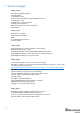
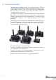
2. Executive summary Marvelmind Indoor Navigation System is an off-the-shelf indoor navigation system designed to provide precise (±2cm) location data to autonomous robots, vehicles (AGV), and copters. It also used to track other objects that the mobile beacon installed on, for example, virtual reality (VR) systems, helmets for construction workers or miners, etc. The navigation system based on stationary ultrasonic beacons which united by radio interface in a license-free band.
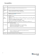
Key capabilities: Parameter Technical Specifications Distance between beacons Reach up to 50 meters in lab conditions. Recommended distance is 30 meters (Transducer4 to Transducer4 looking straight at each other and other transducers are off) Coverage area - Reach up to 1000 m2 with the Starter Set configurations Location precision - Absolute: 1–3% of the distance to the beacons Differential precision: ±2 cm - 0.
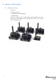
3. Basics of the system 3.1 What’s in the box Starter Set: - 4 x Stationary beacons 1 x Mobile beacon (aka “hedgehog”) 1 x Modem/Router * Starter set includes beacons without IMU. Exact appearance may wary depending on the hardware version.
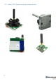
3.2 Indoor Navigation System architecture Marvelmind Indoor Navigation System provides high-precision (± 2 cm) indoor coordinates for autonomous robots and systems (“indoor GPS”).
3.
4. System elements 4.1 Stationary beacons - Should be mounted on walls and ceilings—above the robot and with ultrasonic sensors facing down—to provide the most robust unobstructed ultrasonic signal coverage to the robot. However, for automatic landing and indoor navigation of copters, for example, it is recommended to install mobile beacon horizontally downwards looking on the belly of the copter.
4.2 Mobile beacon (“hedgehog”) - 11 - The mobile and stationary beacons can be easily interchanged by selecting the option in the Dashboard - The mobile beacons designed placed on a robotic vehicle, copter/drone, AGV, or helmet to trace its location. Formally speaking, location of the mobile beacon is traced—not the robot itself. Since the sizes and the location of the central point of the mobile beacon and the robot are different, the difference taken into account in the robot’s software (SW).
4.
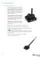
4.4 13 Modem/router - Modem is the central controller of the system. It must be powered at all time when the Navigation System is working. It recommended that an active USB hub used for that purpose or even a regular cellular phone USB power supply.
4.5 Charging beacons and other details - The Beacon has 5 sensors (transducers): RX1, RX2, RX3, RX4, and RX5 - Charging occurs automatically every time a USB charger is attached to the board. LED 1 is active and lights red - It takes 1–2 hours to fully charge the board’s battery - If you plan using a charger for permanent powering of the beacon, make sure that the power source is not noisy (+5V is not noisy). The performance can be monitored by going to Dashboard => View => Oscilloscope.
4.6 DIP switch modes 1) Power = OFF, DFU = OFF: Charging is possible; beacon disconnected from internal battery. This mode recommended if you want to keep the battery fully charged for a long time and to store the beacon on the shelf ( 2) Power = ON, DFU = OFF (pictured below): Normal working mode for the beacon. The beacon fully powered and will wake up every a few seconds to monitor radio signals from the modem.
5. Setting up the system 5.1 16 First setup of your device - The steps below describe the very first time you set up of the system. - Unpack the system. Watch the help video: https://youtu.be/IyXB3UXHdeQ Note that the video is shot for the previous hardware (HW) version (4.5) - Check that your boards charged; see that all switches on the beacons are in the correct position (Power = ON; DFU = OFF). See the paragraph DIP switch modes - Press the RESET button on each beacon.
5.2 HEX programming - After charging boards, download the latest stable SW package from https://marvelmind.com/pics/marvelmind_SW_2017_11_15.zip - Run the Dashboard and update the SW for all beacons and modem using Dashboard => Firmware => Choose the file => Program - If you see the message “Not found modem connection to computer through USB” in the Dashboard, it usually means that the driver is not installed.
5.3 DFU Programming DFU programming or SW uploading used when HEX SW uploading in the Dashboard cannot be used.
- Choose the DFU driver (file) for the beacon - Click the UPGRADE button - After a couple of seconds, the DFU will be uploaded to the beacon. Make sure it actually takes 1–3 seconds and does not happen immediately. Otherwise, the SW has not really uploaded. If the DFU appears to upload immediately, check the "Choose" button you used or change the version of DfuSe SW you selected. - Move the DIP switch into Power = ON, DFU = OFF - Start the Dashboard and press the RESET button on the beacon.
- Start the Dashboard and press RESET button If you experience difficulties in DFU programming, please check and do the following: 20 - Change your operation system (from Windows 10 to Windows 7 or vice versa).
5.4 Setup the Dashboard SW If you’ve uploaded the latest firmware for all of the boards you can start to activate the system 21 - While the beacon and modem are connected to the Dashboard, click the DEFAULT button on the Dashboard to upload the default settings - Write down the beacon’s address for future use or change the address at your convenience as shown here - Press the RESET button on your beacons and modem after programming.
- 22 It may take up to 8 seconds for the beacons to wake up - If the modem is not active and is not powered, the beacons will go into sleep mode automatically after 1 minute - The system may run the frequency search, if it is the very first time you’re waking up the beacons. If this step does not work, disconnect the modem and connect that beacon again via USB.
- 23 If the map does not form well, check the table of distances in the left corner of the Dashboard.
- If you see in the table some empty cells or marked yellow/red, it is an indication that distances between Some beacons are measured inconsistently or not measured at all. Try to re-position them because usually there is an obstruction of some sort in the between the beacons. It also may be different height of beacons’ positon. Reset all these beacons. Use View => Table of distances to monitor the measured distances between beacons 24 - Freeze the map by clicking the button.
- If you see on the devices’ panel in the Dashboard that the beacon is colored orange, it means there are some differences in some of the settings between beacons. For example, some sensors may be off or some ultrasonic or radio settings may be different. You can change the settings for sensors manually by clicking on the panel on the upper right corner of the Dashboard to change the cells from gray to green to turn on sensor.
5.5 Dashboard signs, menu and parameters The main parameters of the connected band are shown on the long panel on the right side of the Dashboard - Check our help video for a deeper understanding of the Dashboard menu - Here is the detailed explanation of the beacons’ settings 5.5.1 CEILING and MIRRORING buttons on the Dashboard 5.5.
5.5.
5.6 SW feature descriptions Here we describe the most useful and main features in the Dashboard. 5.6.1 Submaps feature Submaps is a very powerful feature that allows building large maps (full business center, factory, warehouse with total area of 10,000...300,000 or more) based on smaller submaps (30...1000m2) A submap is a part of the map. It includes a subset of used beacons covering part of the navigation area. Current version of Marvelmind system can include up to 10 submap.
Starting submaps • Hedgehogs do not belong to any submap and can move between submap areas. Hedgehogs can be served not by only one submap at the same time. By default, the map consists of single sub-map, Submap0, • After adding new beacons to the system (waking them up), they appear in the first not frozen submap, or in the Submap0 if all the beacons are frozen • Pressing the “+” button, add new empty submap to the system. • Press the button with the submap number (Submap0, Submap1 etc.
• The system after adding beacons to the Submap0, adding new submap and the selection of Submap0 • Now we have 4 beacons, all in Submap0 (it can be seen near the table of distances) • When the submap selected, the context menu of beacons buttons (available by right clicking the mouse) have the functions of adding and removing the beacons from the submap. In the picture above, we are removing beacon 3 from Submap0.
• Now there are two beacons in Submap1, so this submap is built. “Submap 0” is built as well. Now we can freeze both submaps • If pressing the “freeze map” button when the submap is selected, only the selected submap will be frozen. If pressing the “freeze map” button when the modem button is selected, all submaps will be frozen • Now we have two good submaps, but they are not correctly located relative to each other.
• Submaps can be removed from system using the context menu of the submap selection button (available with a right mouse click)M1/M2 parameter used for precise superposing submaps which do not have common beacons. So submaps cannot be aligned automatically To align submaps: 1. Build the system like in previous instruction (1-11) 2. Put M2 in mode on by clicking the icon. Place the hedgehog near the boundary between two submaps.
Next step is to set service zones 33 • Double click on submap icon and choose “Set area on map” in order to tell the system which beacons will serve in which areas and to make the map with submaps far more robust • Put points around submap, move them to provide service area for current submap. Service areas will cross each other.
5.6.2 Paired beacons Two hedgehogs can be paired and work together as a single beacon without update rate reduction. Moreover, each beacon streams out in this mode not only its own location, but direction where the pair is facing. This feature hugely simplifies autonomous driving and flight. Here is updated protocol with the changes Please, also check our help video. Follow these steps: 1. Wake up stationary beacons and freeze the map 2.
5.6.3 Load and save map Save Map/Load Map feature and buttons are active now. You can build a very complex map with submaps and save all settings for the map, submaps, and all beacons including their ultrasonic gain, triggers, etc.
5.6.4 Payload streaming Mobile beacon streaming user payload to modem. See the table with speed vs. payload. All measurements were made with update rate setting 16 Hz. Real update rate is limited by distance, radio profile and payload data size System configuration Radio profile kbps 500 (FEC) 2 stationary beacons 3 meters maximum distance 153 (FEC) 38.4 (FEC) 38.4 (no FEC) 500 (FEC) 4 stationary beacons 11 meters distance (limitation distances auto) 153 (FEC) 38.4 (FEC) 38.
5.6.
6. Interfaces Indoor “GPS” system supports many external interfaces that can feed measured location data to an external system (robot, copter, VR, etc.). There are two different ways to obtain the mobile beacons’ location data from the system 1. From the mobile beacons o Each mobile beacon knows its own position and does not know the positions of the other mobile beacons 2.
6.1 39 Beacon HW v4.
6.2 40 Modem HW v4.
7. Advanced system settings and optimization Start using advanced settings only when you know what you are doing If you ran into troubles, connect the beacon or modem to the PC via USB and use the DEFAULT button. It will upload “factory settings” to the board while keeping the device address untracked 7.1 How to place beacons Avoid placing beacons on long sound-conducting objects This is a very rare but may happen in some special circumstances.
There are several ways to reduce impact: Mobile beacons can be placed very close to the source of noise without harm, but stationary beacons should be placed further from the noise because they are receiving the ultrasound, whereas the mobile beacon is emitting the ultrasound 7.2 Using Oscilloscope Monitor ultrasonic signal from one beacon to another Use Dashboard => View => Oscilloscope to monitor ultrasonic signals from one beacon to another.
7.3 Proper ultrasonic signal detection When external noise is high: - Identify the source. Usual suspects: Ultrasonic-based volume or movement detection alarm systems Other robots using ultrasonic Parktronics Sources of very strong white or impulse noise (air guns, air press, cutters, vacuum cleaner, etc.) Rotors of drones/copters Marvelmind Indoor Navigation System uses proprietary 31kHz frequency for ultrasonic signal and employs additional filtering to combat external noise.
7.4 Using hedgehog.log file The system automatically records all measured positions in the hedgehog.log file that is stored in the same folder as the Dashboard.exe file The data is written in csv format; each line describes the position of one of the hedgehogs at a certain moment The line format is described here 7.5 System accuracy evaluation 1) Accuracy of distances measurement.
7.6 Enable special mode of the Dashboard To switch the beacon into the mode of emitting constant radio frequency, you need to enable special mode of dashboard with additional functions.
7.
7.8 Settings to obtain correct north direction In some cases, it is necessary to obtain a correct north orientation of the map for NMEA output from Marvelmind system. For example, when using a Marvelmind mobile beacon as the navigation data source for Pixhawk installed on a copter, correct north is required for correct yaw control of the copter. The Marvelmind system cannot determine north automatically, so the user should make corrections after building and freezing the map.
7.9 Communication of Pixhawk with Marvelmind mobile beacon The Marvelmind mobile beacon can be connected to Pixhawk (and to any other hardware or software that inputs GPS according to the NMEA0183 protocol). The mobile beacon can send GPS data via UART and USB (virtual UART) interfaces.
7.10 Sending path to robot 1. The dashboard sends request to modem via USB. Procedure of sending these requests in dashboard is shown on second screenshot. This format of request is described in section 8 of modem protocol: https://marvelmind.com/wp-content/uploads/2017/08/modem_usb_protocol_2017_01_27.pdf 2.
3. the hedgehog communicates with robot via UART. Hegehog sends data according to section 2.3.1 of this protocol: https://www.marvelmind.com/pics/marvelmind_beacon_interfaces_v2017_09_13.pdf The robot should confirm receiving data by response packet shown in section 2.3 This communication on the robot side is implemented in the Arduino example on our site.
7.11 Proper ultrasonic coverage The single most important requirement for the system to work well is to have proper ultrasonic coverage Each sensor has an ultrasonic beam of ~90 degrees. Outside of that range, the emitting power and sensitivity drops quite rapidly. From the left, right, or back of the ultrasonic sensor, the signal is highly attenuated. Thus, it is crucial to provide proper ultrasonic coverage for the area where the robot will be moving.
- Example of proper positioning of the mobile beacon can be found here: https://youtu.be/PFgNPkLGCDk. The beacon is placed horizontally and above other objects that can cast a shadow on the stationary beacons Keep the radio signal’s strength under control - The RSSI (Dashboard => right menu) of any beacon/modem must not be higher than -25dBm. Otherwise, the system may malfunction. It is recommended the distance between the modem and beacons be no less than 0.5–1m.
Use 30 - 50 periods (pulses) in settings instead of the default 5.
7.12 Sensors settings: example for 2D and mobile beacon Beacon 3 Beacon 2 2D Hedgehog 7 Beacon 2 RX1 and RX4 emit ultrasound in normal mode for better ultrasonic signal exchange with Beacon 3. In frozen mode RX2 added as working sensor.
7.13 Powering beacons Modes of operations 1. Stationary beacons powered from a clean source of +5V USB 2. Mobile beacon powered from a clean source of +5V USB from a robot 3. Operations based on internal LiPol 3.7V 1000 mAh cell - Typical power consumption in deep sleep mode is 50uA, which provides ~2 years of shelf time with a regular 1000mAh battery.
8. 8. Frequently Asked Questions Please check this forum for more information. Here we will answer the most common questions 1 What is the proper way to place the beacons? The actual distance between beacons must be ≤ 30 m.
9 What if losing hedgehog after 0.6 m By default, the service area for mobile beacons is limited and mobile beacon not positioning far from stationary beacons. The limit is 1.5x times the maximum distance between the stationary beacons. To expand the service area, please follow the instructions shown in the attached screenshot.
9. Contacts For additional support, please send your questions to info@marvelmind.