
Operating instructions


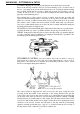


If the stove is a YUKON fitted with a straight flue socket, the clearance measurement is
taken from the belly ring and 80mm must be added to the minimum clearance shown in
the table. Remember, these minimum clearances may be significantly reduced by suitable
heat shielding. (See later)
Table 1.
MINIMUM CLEARANCES TO UNSHIELDED HEAT SENSITIVE WALLS.(mm)
PITTSBURGH FATSO OREGON KLONDIKE YUKON
Rear Clearance 850 700 750 800 575 †
Side Clearance 900 § 725 « 725 « 900 § 750 §
Measured to rear of flue.
§ Measured to belly ring.
« Measured to side of cook-top.
† Measured to rear of flue — add 80mm when measuring to belly ring.
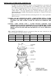
WALL SHIELDING
The minimum distances between the stove and heat sensitive walls, (shown in Table 1),
may be reduced significantly by fitting a 180° polished stainless steel flue heat deflector
on the flue and suitable heat shield(s) on the adjacent wall(s). Shields must be made of
heat resistant material (such as sheet metal, Harditherm or Supalux) and they must be
mounted on the wall on non-combustible spacers arranged to not obstruct the vertical
flow of cooling air in the space between the shield and the wall. Shields of dense
material such as brick and concrete, when mounted in contact with the wall, are virtually
useless.
Ventilation slots must be provided at the top and bottom of each shield, each slot having
a cross-sectional area not less than half the width of the shield multiplied by the spacing
depth. The slots should, as far as possible, extend across the full width of the shield.
EXAMPLE: A 1200mm wide shield spaced 25mm from the wall must have ventilation
slots, top and bottom, each of an area not less than 600 x 25 mm
2
, i.e. 15,000mm
2
. So
if the effective length of each slot is 1m, it will need to be 15mm wide.
Three types of shield are recommended:-
Type Layers Spacing Clearance Factor
A One 12mm 0.4 *
B One 25mm 0.3 *
C Two 12 & 12mm 0.2 *
* These factors are valid only for vertical shields or shields within 45˚ of vertical. They
do not apply to shields under horizontal ceilings or ceilings which are less than 45˚ from
horizontal.
To find the reduced minimum distances, multiply the figures in Table 1 by the
appropriate clearance factor.
EXAMPLE: A PITTSBURGH has a normal minimum rear clearance of 850mm and a
side clearance of 900mm. The reduced minimum clearances for type A shielding would
be 850 x 0.4 (340mm) at the rear, and 900 x 0.4 (360mm) at the side.
Table 2.
REDUCED MINIMUM WALL CLEARANCES (mm) WITH A FLUE SHIELD AND WALL SHIELDS
FITTED
POSITION TYPE PITTSBURGH FATSO OREGON KLONDIKE YUKON
REAR A 340 280 300 320 230
REAR B 255 210 225 240 175
REAR C 170 « 140 « 150 « 160 « 115 «
SIDE A 360 290 290 360 300
SIDE B 270 220 220 270 225
SIDE C 180 145 145 180 150
4