Manual Owners & Installation Monaco Gas Fires PLEASE KEEP THESE INSTRUCTIONS FOR FUTURE REFERENCE WARNING Improper installation, adjustment, alteration, service or maintenance can cause injury or property damage. For assistance or additional information consult an authorized technichian, or your Masport Gas Fire Dealer. FOR YOUR SAFETY Do not store or use gasoline or other flammable vapours and liquids in the vicinity of this appliance Installation and service must be performed by authorized personnel.
THE INSTRUCTIONS IN THIS MANUAL APPLY TO MASPORT MONACO GAS FIRES. THE MODELS COVERED ARE:For use with Natural Gas:MONACO ACC NG, MONACO ECS NG. For use with Liquid Propane Gas (LPG):MONACO ACC LP, MONACO ECS LP.
WARNING. Installation of all gas appliances MUST be carried out only by an Authorised Installer. The heater must be installed according to these instructions and in compliance with all relevant building, gas-fitting, electrical and other Statutory Regulations (e.g. AS 5601 (AG-601), NZS 5261). Any shortcomings in the appliance and flue installation will be the responsibility of the installer, and Masport Ltd will not be accountable for any such failings or their consequences.
OPERATING INSTRUCTIONS DO NOT PLACE ARTICLES ON OR AGAINST THIS APPLIANCE. DO NOT USE OR STORE FLAMMABLE MATERIALS NEAR THIS APPLIANCE. DO NOT SPRAY AEROSOLS IN THE VICINITY OF THIS APPLIANCE WHILE IT IS IN OPERATION. LIGHTING AND RUNNING THE FIRE:• Open the gas supply valve behind the appliance, if fitted. CAUTION: If the main burner has been alight, wait two to three minutes to allow it to cool before relighting it. ACC MODELS:These can be in three configurations.
• Check the display on the remote control. If it reads ‘OFF’, aim the remote control toward the receiver and press the centre button on the remote to switch it to ‘ON’. When the display shows ‘ON’, the SET TEMP will be displayed below the ROOM TEMP. For the burner to light, the SET TEMP must be higher than the ROOM TEMP. Raise the SET TEMP, if necessary, by pressing the right hand button. • Turn the PILOT control fully anticlockwise to the ‘ON’ position and the fire will light at full heat.
• The lower rocker switch on the handpiece controls the fan, switching it to ‘OFF’, ‘LOW’, ‘MEDIUM’ and ‘HIGH’ sequentially. NOTE. The fan is also controlled by an internal switch which will not permit it to start until the fire is hot (about ten minutes from cold on high fire) and will keep it running after the fire goes out. The handpiece will not start the fan during the warm-up period, but it can pre-select the speed at which the fan will start once the firebox is hot.
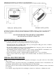
INSTALLING INSTRUCTIONS HEATER DIMENSIONS 5
MINIMUM INSTALLATION CLEARANCES (To heat sensitive surfaces) g g NOTE: The clearances shown are for fire hazard only. For durability of finishes or surfaces you should contact the relevant manufacturer for their specification. MASPORT accepts no responsibility for the deterioration of surfaces or finishes.
THERMOSTATS ACC Models. Two accessory options are available: • The hand-held IRRC Model 300 non-programmable remote thermostat. • The wall-mounted programmable thermostat. Instructions for installing both options are supplied with them. ECS Models. An optional battery powered wall-mounted programmable thermostat is available. GAS PRESSURE ADJUSTMENT. All pressure adjustments must be made while the heater is operating on the ‘HIGH’ setting. ACC NG and ACC LP.
3. Cut appropriate holes through the ceiling and roof material and install the flue in accordance with the instructions accompanying it, taking care to provide any safety clearances specified in the instructions (usually 25mm between the flue shield and any nearby combustible material). The installation must meet the requirements of AS 5601 (AG 601) or NZS 5261 as appropriate.
TEST FIRING It is absolutely essential that the installer test fires the heater before leaving the site. If fitted, open the gas supply valve at the rear of the heater and check all gas joints for leakage using a leak check solution or an electronic ‘sniffer’, NOT a naked flame. Test fire the heater, following the lighting instructions on pages 2, 3 and 4 of this manual. First check that the pilot light ignites satisfactorily. Initially it may take several attempts until the air is purged from the pipeline.
MAINTENANCE INSTRUCTIONS Maintenance must be carried out only by authorised personnel. Minor adjustments can be made with the heater in its normal operating position, but it will be found more convenient to move the heater away from the wall for major work. If it is necessary to move the heater:• Shut off the gas supply at the valve behind the heater. • Remove the access plate on the rear of the cabinet. • Disconnect the gas line at the heater.
GLASS REMOVAL AND ASSEMBLY Carry out these procedures only while the heater is standing upright. 1. Remove the louvre by lifting it upwards and outwards. 2. Remove the dress guard, if fitted. 3. Remove two fastening screws securing the top glass trim. 4. Prise forward the top glass trim and lift it clear. Note. This will release the top edges of the left and right glass retainers. 5. Lift the glass retainers to remove them, keeping a hand on the glass to ensure that it does not fall forward. 6.
ROUTINE MAINTENANCE SCHEDULE We recommend that you have your Masport heater serviced yearly by an Authorised Technician. This periodic maintenance should cover the following points:1. Replace the battery in the igniter module (ACC models only). Access the battery by pulling open the battery cover of the black plastic module mounted on the rear of the heater. One AA alkaline cell required. 2. Clean all air entry points such as primary and secondary air inlet passages. 3. Clean the main injector jet holes. 4.
NOTE: If the supply cord is damaged it must be replaced by the manufacturer or its service agent or a similarly qualified person in order to avoid a hazard.
TROUBLE - SHOOTING The following table lists possible problems and their likely causes. Most of these will require a professional serviceman and we recommend that this work be performed by an Authorised Technician. If a problem cannot be solved after referring to this table, please call the Retailer from whom the appliance was purchased. Refer to your Warranty Card for details of Warranty cover.
PROBLEM POSSIBLE CAUSE(S) SOLUTION Smell of gas in the room. Pipe fittings may be leaking. Check all joints for leaks, including the gas supply system, the pilot light supply tube, the main burner supply tube and all connections to the control valve. Use ONLY a proper leak check solution. NEVER USE AN OPEN FLAME TO CHECK FOR LEAKS. A thin coating of black soot forms inside the glass. Combustion air supply restricted. Clean all primary and secondary air passageways. Over-supply of gas.
ANNUAL SERVICE RECORD DATE SERVICE DETAILS 16 SERVICED BY
Masport Gas Fires are manufactured in New Zealand by MASPORT LTD. 1/37 MT WELLINGTON HIGHWAY. P.O. Box 14-349 Panmure, Auckland New Zealand. A.G.A. Approvals: Monaco ACC NG, Monaco ACC LP – Both Certificate No. 5656 Monaco ECS NG, Monaco ECS LP – Both Certificate No.