Manual Owners & Installation LISTINGS AND CODE APPROVALS PG36 Gas Log Fireplace Models: PG36NG3-R PG36LPG3-R PLEASE KEEP THESE INSTRUCTIONS FOR FUTURE REFERENCE WARNING: Improper installation, adjustment, alteration, service or maintenance can cause injury or property damage. Refer to this manual. For assistance or additional information consult an authorised installer, service agency or the gas supplier.
TO THE NEW OWNER: Congratulations! You are the owner of a state-of-the-art Gas Log Fireplace by FPI FIREPLACE PRODUCTS INTERNATIONAL LTD. The PG36 has been designed to provide you with all the warmth and charm of a wood fireplace at the flick of a switch. The model PG36 has been approved by the Australian Gas Association for both safety and efficiency. As it also bears our own mark, it promises to provide you with economy, comfort and security for many trouble free years to follow.
TABLE OF CONTENTS DATA BADGE OPERATING INSTRUCTIONS Data badge ....................................................................4 Adjusting Flame Height ...............................................27 Summary Of Controls .................................................27 Pilot Adjustment ...........................................................27 Normal Operating Sounds Of Gas Appliances ............27 Copy Of The Lighting Plate Instructions .....................
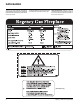
DATA BADGE This is a copy of the label that accompanies each PG36 Zero Clearance Room Sealed Gas Fireplace. We have printed a copy of the contents here for your review. The label is located on the front inside base of the unit, visible when the bottom louvre is open. DATA BADGE NOTE: Regency® units are constantly being improved. Check the label on the unit and if there is a difference, the label on the unit is the correct one.
INSTALLATION IMPORTANT MESSAGE SAVE THESE INSTRUCTIONS The PG36-NG or PG36-LPG Room Sealed Fireplace must be installed in accordance with AS5601-2004 and NZS 5261 5261 and these instructions. Carefully read all the instructions in this manual first. Consult the "authority having jurisdiction" to determine the need for a permit prior to starting the installation.
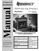
INSTALLATION LOCATING YOUR FIREPLACE 1) When selecting a location for your fireplace, ensure that the clearances outlined on this page are met. 2) P r o v i d e a d e q u a t e c l e a r a n c e s f o r servicing. 3) The appliance must be installed on a flat, solid, continuous surface (e.g. wood, metal, concrete). This may be the floor, or raised up on a platform to enhance its visual impact.
Regency® PG36-3 Gas Log Fireplace Note: A non-combustible mantel may be installed at a lower height if the framing is made of metal studs covered with a non-combustible board. Note: Ensure the paint that is used on the mantel and the facing is "heat resistant" or the paint may discolour. These drawings are to scale at 1:6 (one inch = 6 inches) Mantel can be installed anywhere in shaded area or higher using the above scale.
INSTALLATION FRAMING AND FINISHING 1) Determine the total thickness of facing material (e.g. drywall plus ceramic tiles) to allow the finished surface to be flush with the front of the unit. Total facing thickness can vary from 1/2" (13mm) to 1-1/4" (32mm) thick. 3) For exterior walls, insulate the enclosure to the same degree as the rest of the house, apply vapour barrier and drywall, as per local installation codes. (Do not insulate the fireplace itself.
INSTALLATION UNIT ASSEMBLY PRIOR TO INSTALLATION The Top Facing Support, the Side Nailing Strips and the 2 Top Standoffs must be correctly positioned and attached to the top before unit is slipped into position. Top Standoff Assembly The top standoffs are shipped in a flat position and must be folded into shape and attached. Screw Position Facing Material Depth A B C* 1/2" 7/8" 1-1/4" / 13mm / 22mm / 32mm * For "C" screw position the top facing support is reversed.
INSTALLATION EXTERIOR FLUE TERMINATION LOCATIONS Minimum clearances required for balanced flue terminals or the flue terminals of outdoor appliances according to AS5601-2004 (AGA gas installation code) or NZS 5261 (New Zealand) Minimum Clearance (mm) a b c d e f g h j k Below eaves, balconies or other projections: - Appliances up to 50 MJ/h input 300 - Appliances over 50 MJ/h input 500 From the ground or above a balcony 300 From a return wall or external corner 500 From a gas meter (M) 1000 From an electr
INSTALLATION FLUEING Regency® Direct Vent System (Flex) Horizontal Terminations Only These flueing systems, in combination with the PG36 Room Sealed Gas Fireplace, have been tested and listed as a Direct Vent type flue system by the Australian Gas Association. The location of the termination cap must conform to the requirements in the Flue Terminal Locations diagram in the "Exterior Flue Termination Locations" section.
INSTALLATION SIMPSON DURA-VENT FLUEING Horizontal or Vertical Terminations The Simpson Dura-Vent Co Axial Flue System offers a complete line of component parts for installation of both horizontal and vertical installations. Many items are offered in decorative black, as well as galvanized finish. We recommend using the galvanized finish for installation with the PG36.
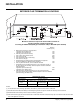
INSTALLATION FLUEING ARRANGEMENTS - HORIZONTAL TERMINATIONS SIMPSON DURA-VENT DIRECT FLUE GS SYSTEM and REGENCY® DIRECT FLUE SYSTEM (FLEX) (LPG & NG) The diagram shows all allowable combinations of vertical runs with horizontal terminations, using one 90o elbow (two 45o elbows equal 2 0 one 90o elbow). 4 Note: Must use optional flue adapter (Part # 510-994) when using Simpson Dura-Vent pipe. 38 M eters 3.5 3 2.5 2 1.5 1 0 0.5 36 5.
INSTALLATION FLUEING ARRANGEMENTS - HORIZONTAL TERMINATIONS SIMPSON DURA-VENT DIRECT FLUE GS SYSTEM and REGENCY® CO AXIAL FLUE SYSTEM (FLEX) (LPG & NG) The diagram below shows examples of horizontal termination arrangements using two 90o elbows (two 45o elbows equal one 90o elbow). Note: 1) 2) 3) 4) A maximum of two 90o elbows are permitted. A minimum of 6 ft. (1.8m) vertical from base of unit is required if two 90o elbows are used. Minimum distance between elbows is 2 ft. (0.6m).
INSTALLATION FLUEING ARRANGEMENTS - VERTICAL TERMINATIONS SIMPSON DURA-VENT CO AXIAL FLUE GS SYSTEM (LPG & NG) The PG36 is approved for a 23 ft. (7.0m) vertical, with a maximum 12 ft. (3.7m) horizontal offset using two 90o elbows (two 45o elbows equal one 90o elbow) with Simpson Dura-Vent Co Axial Flue GS flue systems for LPG and NG, as per diagram 1. The PG36 is approved for a 37 ft. (11.3m) straight vertical, including a 20" (0.
INSTALLATION The PG36 is approved for a 37 ft. (11.3m) straight vertical, with Simpson Dura-Vent Co Axial Flue GS flue systems for LPG and NG, as per the diagram 3. The shaded area in the diagram 3 shows all allowable combinations of straight vertical and offset to vertical terminations with Simpson Dura-Vent Co Axial Flue GS flue systems for LPG and NG. Maximum two 45o elbows allowed. • • • Flue must be supported at offsets Firestops are required at each floor level and whenever passing through a wall.
INSTALLATION HORIZONTAL TERMINATIONS Install the flue system according to the manufacturer's instructions included with the components. 1) Set the unit in its desired location. Check to determine if wall studs or roof rafters are in the way when the flueing system is attached. If this is the case, you may want to adjust the location of the unit. Rough in the gas preferably on the right side of the unit and the electrical (junction block is on the left side) on the left.
INSTALLATION VERTICAL TERMINATIONS 1) Maintain the 1-1/4" (32mm) clearances (air spaces) to combustibles when passing through ceilings, walls, roofs, enclosures, attic rafter, or other nearby combustible surfaces. Do not pack air spaces with insulation. Check seciotn "Simpson Dura-vent Flueing" for the maximum vertical rise of the flueing system and the maximum horizontal offset limitations. 2) Set the gas appliance in its desired location.
INSTALLATION PG36-NG3 System Data GAS CONNECTION For 0 to 4500 feet altitude Burner Inlet Orifice Sizes: #37( 2.65mm) The gas line should be rigid pipe. Copper may also be used if approved by AS5601-2004. Max. Input Rating Min. Input Rating 33 mj 20 mj The gas connection at the valve is 1/2 male. For minimum and maximum supply pressure see the System Data Table. Supply Pressure min.1.13 kPa GAS PIPE PRESSURE TESTING Manifold Pressure (High) 0.9 kPa Electrical: 240 V A.C. System.
INSTALLATION Conversion Kit For NG To LPG Model #516-969 THIS CONVERSION MUST BE DONE BY A QUALIFIED GAS FITTER IF IN DOUBT DO NOT DO THIS CONVERSION!! Conversion Kit 516-969 Contains: Qty. Part # 1 904-390 1 908-528 1 918-590 1 918-334 1 910-920 Description Burner Orifice #52 Red "LPG" label Label "Converted to LPG" Instruction Sheet LPG Pilot Orifice 8) Lift the pilot assembly and remove the pilot tube from the pilot holder using a 11mm wrench.
INSTALLATION 21) Stick the conversion label "This unit has been converted to LPG" on the control box cover. A B C 22) Reverse steps 19 and 18. 23) Turn on gas supply and plug in power cord. 24) Adjusting the Outlet Pressure All the adjustments must be carried out in the following order: Remove the modulator plastic cap (A) using needle nose pliers. Maximum pressure: Turn the unit ON to its highest input rating. Screw in the nut (B) to increase the outlet pressure and screw it out to decrease it.
INSTALLATION OPTIONAL BRICK PANELS LOG SET INSTALLATION 1) Undo the bottom 2 door latches and open and remove glass door. Remove logs. Read the instructions below carefully and refer to the diagrams. If logs are broken do not use the unit until they are replaced. Broken logs can interfere with the pilot operation. Note: The logs must not be in the unit. 2) Insert the back brick panel first by carefully slipping it between the back wall of the firebox and the rear log bracket.
INSTALLATION 02-49 02-53 8) Position Log 02-54 across the cutouts in Logs 02-51 and 02-53. The notch in the bottom right end fitting against the 5th grate tab. 10) Place the embers on the front of the burner tray in the places shown on the photo. 02-51 02-54 6) Place the bottom left front edge of Log 02-55 against the rear bracket on the burner tray and rest the log on the cutout on Log 02-53. 02 -5 3 Place embers in these 3 locations on the burner tray.
INSTALLATION 11) Test fire to ensure proper light off (make sure flame flows smoothly from one end of burner to the other). If there is any flame hesitation, check that area for any blockage of the burner ports. 02-49 12) Install flush glass and bay glass (if used) as per instructions in this manual. 02-55 02-52 02-50 53 2- 02-51 02-54 0 STANDARD FLUSH DOOR The standard flush door comes with a black frame.
INSTALLATION WIRING This heater requires a 240V A.C. supply for the gas control to operate. A 240V A.C. power supply is needed for the fan/blower operation. Caution: Ensure that the wires do not touch any hot surfaces and are away from sharp edges. CAUTION: Label all wires prior to disconnection when servicing controls.
OPERATING INSTRUCTIONS REMOTE CONTROL LIGHTING INSTRUCTIONS Use the Regency® Remote Control Kit approved for this unit. Use of other systems may void your warranty. 1) Plug the power cord into a power outlet. The remote control kit comes with a hand held transmitter and a wall mounting plate. 2) Press and release the ON/OFF button once to start the unit. 1) Choose a convenient location to mount the hand held transmitter, protection from extreme heat is very important.
OPERATING INSTRUCTIONS ADJUSTING FLAME HEIGHT There are six flame settings that can be adjusted by pressing and releasing the plus (+) and minus (-) FLAME button. The FLAME setting button is located on the control panel in behind the pedestal door. SUMMARY OF CONTROLS PILOT ADJUSTMENT Periodically check the pilot flames. The correct flame pattern has 3 strong blue flames.
OPERATING INSTRUCTIONS COPY OF THE LIGHTING PLATE INSTRUCTIONS FOR YOUR SAFETY READ BEFORE LIGHTING This appliance must be installed in accordance with local codes, if any; if not, follow the current CAN1-B149/ANSI Z 223.1 (Australia: AS5601-2004, New Zealand: NZS 5261) WARNING: If you do not follow these instructions exactly, a fire or explosion may result causing property damage, personal injury or loss of life.
MAINTENANCE MAINTENANCE INSTRUCTIONS Any maintenance required accessing the glass door of the unit must be performed by an authorized service person. 1) Always unplug the power cord before cleaning. For relighting, refer to lighting instructions. Keep the burner and control compartment clean by brushing and vacuuming at least once a year. When cleaning the logs, use a soft clean brush as the logs are fragile and easily damaged.
MAINTENANCE GOLD Or BRASS LOUVRES & TRIM In the event that you break your glass by impact, purchase your replacement from an authorized Regency® dealer only, and follow our step-bystep instructions for replacement. The 24 carat gold plated or brass finish on the trim requires little maintenance, and need only be cleaned with a damp cloth. DO NOT use abrasive materials or chemical cleaners, as they may harm the finish and void the warranty. Clean any fingerprints off before turning the unit on.
MAINTENANCE REMOVING VALVE TRAY 1) Shut off the gas supply. 2) Remove the louvres. 3) Open the flush door and remove door. 4) Remove the logs. 5) Remove the burner/grate assembly by removing the left and right side Philips head screws and then lift the burner assembly out. 9) Remove the front cover by removing the 2 screws which secure the front cover to the valve tray. Left Side Shown Front Cover 10) Unplug the 2 orange wires from the Gas Pressure Electric Modulator.
MAINTENANCE FAN REPLACEMENT 1) Shut off the power supply. 7) Unplug the black wire from the resister. 2) Remove the top louvre. 8) Carefully slide the fan to the front left side of the unit. 3) Remove the glass door. 9) Remove the screw which holds the ground wire and disconnect all electrical connectors that are attached to the fan. 4) Remove the 3 screws which secure the manual control box to the bottom louvre and remove the bottom louvre. Ground Wire Manual Control Box 10) Pull out the fan.
PARTS LIST ELECTRONIC COMPONENTS PARTS LIST 910-915 910-082 910-089 910-088 910-912 910-084 910-526 910-080 910-906 910-521, 910-522, 910-523 FG37 FG38 910-083 910-514 910-916 FG39 PG33 PG36 HG35 PG121/PG131 N/A N/A N/A N/A N/A 910-909 Fan Resistor 910-915 Intermittent Pilot 910-082 Direct Spark Ignitor N/A N/A 910-089 Flame Cable 910-088 Spark Cable 910-084 Control Box 910-526 Manual Control N/A N/A N/A 910-080 Valve 910-521 Control Box Cable (1) 910-522 Control Box Cable (2) 910
PARTS LIST MAIN ASSEMBLY 3) 4) 14) 15) 17) 20) 21) 22) 23) 24) 27) 28) 30) 31) Part # Description 948-045 948-025 Chain Spring 910-169/P 910-904 910-809 910-714 Fan Motor Wire Harness (Fan End) Wire Harness (Stove End) Power Cord (240 V) 510-026 948-253 * 510-033 510-064 510-153 510-011F 511-044 * * * * Hinge Bracket - Left/Right Door Handle Wire Holder Clip Top Nailing Strip Side Nailing Strip Baffle Plate Standoff - Top Standoff - Side/Back Outer Flue Collar Inner Flue Collar Assembly Gasket for F
PARTS LIST BURNER ASSEMBLY & LOG SET Part # Description 516-574/P 516-576/P 52) * 53) 430-055 59) * 65) * 66) 910-915 904-240 904-390 910-920 936-170 67) * 68) W840470 Valve Assy - NG Valve Assy - LPG Valve Tray -NG Gasket - Valve Access Plate Firebox Base Pilot Bracket Intermediate Pilot Assy.
PARTS LIST BAY FRONT ASSEMBLY Part # 103) 107) 108) 111) 780-931 940-092/P 936-243 940-094/P 902-285 Description Part # Bay Front Complete Side Glass Glass Gasket - Soft Fibre Black Center Glass Brick Panel - Bay 780-938 780-936 112) * Bay Front Trim - Brass Bay Front Trim - Steel Bay Front Trim -Top/Bottom 780-934 113) * 114) * Bay Door Trim - Gold Bay Door Trim-Gold-Bottom Bay Door Trim-Gold-Top Description 510-988 510-990 510-992 510-993 115) * 116) * Bay Louvres - Black Bay Louvres - Gold/Bla
PARTS LIST FLUSH FRONT ACCESSORIES Part # Description 132) 512-518 135) 940-090/P 136) 936-155 904-691 Flush Door Assembly Glass (Flush) Glass Gasket (Tadpole) U-Clip 510-920 510-921 510-922 510-923 138) * 139) * Flush Louvres - Gold/Black Flush Louvres - Brass/Black Flush Louvres - Black Flush Louvres - Steel/Black Flush Louvre Assy-Top Flush Louvre Assy-Btm 510-954 146) * 148) * Barcelona Surround - Black Barcelona Assy Barcelona Louvre Assy 510-932 150) * Flush Glass Trim - Gold (2/Set) Flush Gl
PARTS LIST CAST FACEPLATE ASSEMBLY Part # Description 513-971 201) * 202) * 203) * Cast Faceplates (Set) - Black Metallic Cast Faceplate - Right Cast Faceplate - Top Cast Faceplate - Left 513-991 204) * 205) * Cast Grills (Set) - Black Metallic (Aust. only: 240 volt) Cast Grill - Top Cast Grill - Bottom 513-976 201) * 202) * 203) * Cast Faceplates (Set) - Black Enamel Cast Faceplate - Right Cast Faceplate - Top Cast Faceplate - Left 513-996 204) * 205) * Cast Grills (Set) - Black Enamel (Aust.
WARRANTY Regency® Fireplace Products are designed with reliability and simplicity in mind. In addition, our internal Quality Assurance Team carefully inspects each unit thoroughly before it leaves our door. FPI is pleased to extend this limited lifetime warranty to the original purchaser of a Regency® Product.
© Copyright 2006, FPI Fireplace Products International Ltd. All rights reserved.