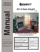
Owners & Installation I31-3 Gas Inbuilt Manual Model: LISTINGS AND CODE APPROVALS These gas appliances have been tested in accordance with AS4553, NZS 5262 and have been certified by the Australian Gas Association for installation and operation as described in these Installation and Operating Instructions. Your unit should be serviced annually by an authorised service person.
REGENCY GAS FIREPLACE INBUILT FIREPLACE TO THE NEW OWNER Congratulations! You are the owner of a state-of-the-art Gas Inbuilt Fireplace by Regency Industries. The Regency Gas Fireplace Series of hand crafted appliances has been designed to provide you with all the warmth and charm of a fireplace, at the flick of a switch. The model I31-3 of this series has been approved by Australian Gas Association for both safety and efficiency.
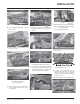
TABLE OF CONTENTS REGENCY GAS FIREPLACE INSERT Operating Instructions Unit Dimensions .......................................................... 2 Safety Label................................................................. 4 Installation For Your Safety ............................................................ 5 Specifications .............................................................. 5 Installation Checklist .................................................... 5 Materials Required ...............
DATA BADGE This is a copy of the label that accompanies each Regency I31-3 Gas Inbuilt fireplace. We have printed a copy of the contents here for your review. DATA BADGE NOTE: Regency units are constantly being improved. Check the label on the unit and if there is a difference, the label on the unit is the correct one. Regency Gas Fireplace Distributed by: Model Gas Type NG Model P36-NG LPG P36-LPG NG I31-3NG LPG 33mj. 31mj. 31mj. 31mj. Manifold Pressure 1.0kPa 2.7kPa .9kPa 2.
INSTALLATION IMPORTANT: SAVE THESE INSTRUCTIONS The Regency Gas Fireplace must be installed in accordance with these instructions. Carefully read all the instructions in this manual first. Note: Failure to follow these instructions could cause a malfunction of the heater which could result in death, serious bodily injury, and/or property damage. Failure to follow these instructions may also void your fire insurance and/or warranty. FOR YOUR SAFETY This appliance requires air for proper combustion.
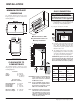
INSTALLATION MINIMUM FIREPLACE DIMENSIONS GAS CONNECTION GAS CONNECTION WARNING: Only persons licensed to work with gas piping may make the necessary gas connections to this appliance. The minimum fireplace dimensions for the Regency gas space heater are shown in the following diagrams: 1) If the appliance is to be installed into an existing chimney system, thoroughly clean the masonry or factory built fireplace. 2) The gas connection is 12" BSP.
INSTALLATION DRAFT DIVERTER CONNECTION 1) Attach the flue to the flue collar on the detachable draft diverter. The flue collar of the appliance will fit inside a standard flue and may be fastened directly to the flue by sheet metal screw. Diagram 1. FLUEING THE APPLIANCE MUST NOT BE CONNECTED TO A CHIMNEY FLUE SERVING A SEPARATE SOLID FUEL BURNING APPLIANCE. This appliance is designed to attach to a 100 mm diameter twin skin or listed gas fuel type flue liner running the full length of the chimney.
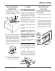
INSTALLATION The smoke should be drawn into the spill tube. If the smoke is still not drawn into the spill tube, turn the unit off and check for the cause of the lack of draft. If necessary, rectify. OPTIONAL BRICK PANEL LOG SET INSTALLATION 1) Unwrap the brick pattern panels from the protective wrapping. Read the instructions below carefully and refer to the diagrams. If logs are broken do not use the unit until they are replaced. Broken logs can interfere with the pilot operation.
INSTALLATION A)02-43 D)02-46 A)02-43 B)02-45 A)02-43 F)02-48 Side View C)02-56 Front edge of rear burner The bottom right edge of Log F)02-48 must sit snugly against the bracket and the front edge of the rear burner. Bracket Pins on Rear Log Support 4) Place Front Right Log B)02-45 on the two pins as shown. Pin Cutout 7) Place the notch in Center Log E)02-47 over Log B)02-45 and across the cutout on Log A)02-43. E)02-47 per instructions in this manual.
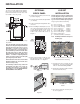
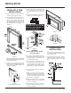
INSTALLATION FACEPLATE & TRIM INSTALLATION 1) Lay the faceplate panels flat, face down on something soft so they don't scratch. 2) Take the top faceplate and align the holes in it with the holes in the side panels. Using the screws provided, attach from the top of the panel (the holes in the top panel are slightly larger than the holes in the side panel to facilitate easier installation). See diagram 1.
INSTALLATION 3) Place the bottom of the flush glass behind the bottom glass trim. Note: Top and bottom louvres and brackets are different. BAY LOUVRES 4) Secure the glass with the two glass clips at the top corners of the glass. Secure glass clips with the screws provided. Do not over tighten as this could break the glass. 2) The bottom louvre has a hinge that is attached (2 screws per hinge) to the lip on bottom of the unit.
INSTALLATION HAMPTON CAST FACEPLATE INSTALLATION NOTE: Do not install Cast Faceplate when unit is installed into a Zero Clearance Unit. 1) Lay the faceplate panels flat, face down on something soft so they don't scratch. 2) Attach the side filler brackets to the left and right sides using 3 screws and washer per side. 5) Connect the ON/OFF switch wires by taking the black and red wires with the blue female ends thru the hole provided and connecting them to the ON/OFF switch.
INSTALLATION 11) Mount the cast faceplate panels onto the insert body, sliding the side filler brackets into the space between the glass and the firebox. Secure using the 4 remaining black screws, 2 per side. Slide side filler bracket into gap between glass and fire box. HAMPTON CAST GRILL INSTALLATION Before the grills are installed, a grill stop bracket needs to be put in place.
INSTALLATION BAROSSA CURVED FRONT INSTALLATION 1) Install bottom louver by matching the holes in louver bracket with holes in firebox frame and secure using 2 screws on each side. 4) Fit plates on back of screen into brackets on top of firebox. Press in to secure from top. Brackets on firebox. Secure louver by using 2 screws. 5) Secure bottom of screen using 1 screw on each side into the brackets fixed onto the firebox in step 3. 2) Pull down louver.
INSTALLATION OPTIONAL REMOTE CONTROL cover in the wall. The remote control is now ready for operation. CAUTION Do not connect the millivolt remote control wires to the 240V wires. Use the Optional Remote Control Kit approved for this unit. Use of other systems may void your warranty. The remote control kit comes with a hand held transmitter, a receiver and a wall mounting plate.
OPERATING INSTRUCTIONS OPERATING INSTRUCTIONS Note: When the glass is cold and the appliance is lit, it may cause condensation and fog the glass. This condensation is normal and will disappear in a few minutes as the glass heats up. Before operating this appliance, proceed through the following check list. 4) Wait five minutes to allow gas, that may have accumulated in the main burner compartment, to escape. If you do smell gas, follow the instructions on the front of this manual.
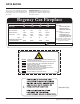
OPERATING INSTRUCTIONS MAINTENANCE INSTRUCTIONS COPY OF LIGHTING INSTRUCTION PLATE FOR YOUR SAFETY READ BEFORE LIGHTING This appliance must be installed in accordance with local codes, if any; if none, follow the National Fuel Gas Code, ANSI Z223.1/NFPA 54, or Natural Gas and Propane Installations Codes, CSA B149.1.
MAINTENANCE CAUTION: ANY SAFETY SCREEN OR GUARD REMOVED FOR SERVICING AN APPLIANCE MUST BE REPLACED PRIOR TO OPERATING THE APPLIANCE. Incorrect flame pattern will have small, probably yellow flames, not coming into proper contact with the rear burner or thermopile. Your Regency stove is supplied with high temperature, 5 mm Neoceram ceramic glass that will withstand the highest heat that your unit will produce.
MAINTENANCE GLASS GASKET If the glass gasket requires replacement use 7/8" flat glass gasket (Part # 936-243) for the Bay Front and for the Flush Front. 7) Remove the Burner Tray by removing the screws on each side of the tray. Push the tray to the left and lift up. FAN MAINTENANCE If your fan requires maintenance or replacement, access to the fan is through the plate on the rear wall of the firebox. NOTE: the unit MUST NOT be operated without the fan access panel securely in place.
MAINTENANCE TROUBLE SHOOTING REGENCY GAS SPACE HEATER SYMPTOM PROBABLE CAUSE CORRECTIVE ACTION 1) Thin black coating [soot]forms on viewing glass. a) Incorrect gas pressure b) Not enough combustion air Check and correct gas pressure if sooting continues open aeration shutter on burner. Note: To clean glass, remove and wipe with cloth or paper towel 2) A change in flame appearance or burner operations a) A change in gas pressure b) Carbon dirt or lint Check gas pressure.
PARTS LIST MAIN ASSEMBLY Part # Description 1) 400-011 Fan Opening Cover 2) 910-169/P Fan Motor (240 V) 4) 910-714 Power Cord 240 Volts 910-707 Wire Harness (Fan end) 910-771 Wire Harness (Faceplate) 5) 400-068 Thermodisc Cover Mounting Plate 6) 400-023 Thermodisc Bracket 7) 910-142 Thermodisc-Fan Auto ON/OFF 8) 910-006 Terminal Block 10) 400-540 Draft Diverter Assembly 11) * Spill Switch Bracket 12) 910-220 Spill Switch 13) * Levelling Bolts 5/16 x 3 Hex Head 948-216 918-001 Part # Description 22) 402
PARTS LIST BURNER ASSEMBLY & LOG SET Part # Description 86) 87) 402-565/P 402-566/P 910-026 910-027 910-190 * 904-702 * 904-240 904-390 910-424 910-426 402-019 402-537 910-034 910-035 * 402-935 402-572 910-386 910-341 Valve Assembly - NG Valve Assembly - LPG RobertShaw Valve - NG RobertShaw Valve - LPG Piezo Ignitor and nut Valve Heat Shield Gasket - Valve Heat Shield Pilot Bracket Burner Orifice NG #37 Burner Orifice LPG # 52 Pilot ON/OFF Extension Knob Flame HI/LOW Extension Knob Grate Assembly Burner
PARTS LIST FACEPLATE ASSEMBLY Part # 87) 88) 91) 92) 93) 94) 95) 96) Description 910-140 910-246 Fan HI/OFF/LOW Switch Burner ON/OFF Switch 403-912 * * * 401-522 * * * Faceplate & Trim Complete - Regular Faceplate Side Right - Regular Faceplate Top - Regular Faceplate Side Left - Regular Trims Packaged - Regular Faceplate Trim Right - Regular Faceplate Trim Top - Regular Faceplate Trim Left Assy - Regular 403-913 141) * 142) * 143) * 401-524 Faceplate & Trim Compelte - Oversize Faceplate Side Right
PARTS LIST BAY & FLUSH FRONT ASSEMBLY Part # Description Bay Door 400-988 102) * 103) * 106) 940-315/P 107) 936-243 108) 940-314/P 110) 902-183 Complete Bay Front c/w Black Trim Glass Retainer Side (Top & Btm) Glass Retainer Front (Top & Btm) Side Glass Gasket Center Glass Bay Brick Panel 400-935 400-989 111) * 112) 904-196 113) * Bay Door Trim Set - Gold Bay Door Trim Set - Steel Bay Door Trim Top 1" Round Ceramic Magnet Bay Door Trim Bottom 24 Part # Description Flush Door 149) 400-531/P 107) 15
PARTS LIST HAMPTON CAST FACEPLATE ASSEMBLY Part # 403-911 403-916 Description Cast Faceplates (Set) - Black Metallic Cast Faceplates (Set) - Black Enamel 187) * 188) * 189) * Burner On/Off Switch Fan Speed Control Knob - Black Cast Surround 201) * 202) * 203) * 205) * 194) * Cast Faceplate - Right Cast Faceplate - Top Cast Faceplate - Left Flush Glass Frame Mounting Flange 207) 402-981 402-986 Cast Grill (Set) - Top & Bottom - Black Metallic Cast Grill (Set) - Top & Bottom - Black Enamel *Not availa
NOTES ___________________________________________________ ___________________________________________________ ___________________________________________________ ___________________________________________________ ___________________________________________________ ___________________________________________________ ___________________________________________________ ___________________________________________________ ___________________________________________________ ______________________________________
WARRANTY Regency Fireplace Products are designed with reliability and simplicity in mind. In addition, our internal Quality Assurance Team carefully inspects each unit thoroughly before it leaves our door. Regency Industries Ltd. is pleased to extend this limited lifetime warranty to the original purchaser of a Regency Product.
© Copyright 2009, FPI Fireplace Products International Ltd. All rights reserved.