XCELLENCE SERIES X12CE - X15CE - X15LTE - X18WE Pol. Ind. Norte - Perpinyà, 25 08226 TERRASSA info@master-audio.com Copyright © 2012 All rights reserved master-audio.
ENGLISH CAUTION WARNING: To reduce the risk of fire or electric shock do not expose this equipment to rain or moisture RISK OF ELECTRIC SHOCK DON’T OPEN Safety Instructions 1. All safety instructions must be read before using this device. 2. The exclamation mark in the triangle indicates internal components which if replaced can affect safety. 3. The lightning symbol within the triangle indicates the presence of dangerous uninsulated voltages. 4. This device must not be exposed to rain or humidity.
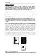
Master Audio 1. INTRODUCTION 1.1. General product information Master Audio thank you for the trust placed in our Xcellence loudspeaker systems. The Xcellence series combines the convenience of a self-powered system and the flexibility of the DSP (digital system processing) for cabinet control.
Master Audio - Ethernet connectivity. Overvoltage protection (>250V-400V). One 15” woofer in neodymium (4” voice coil). One 3” voice coil diameter, titanium diaphragm compression driver. 60º x 50º rotatable horn. Birch plywood construction. Polyurea black textured paint finish. Frontal steel grille with acoustically transparent grey cloth. X18WE Subwoofer - Self-powered cabinet. 2400W amplifier for bass range. 24-bit AD/DA converters with 112dB dynamic range, 96kHz sampling rate.
Master Audio between 50Hz-20kHz (-10dB) for X-12CE and 53Hz-18kHz (+/- 3 dB) with a usable bandwidth between 45Hz-20kHz (-10dB) for X-15CE. They have 1000W continuous amplification (800W + 200W), thermal protection, output short circuit protection, maximum power limiters for each channel, and protection against overvoltage. The DSP includes 5 presets which can be selected either accessing the cabinet’s rear control panel or via the computer with Ethernet connection.
Master Audio P1-FACTORY Flat response • Standard preset P2-NEARFIELD -3dB mid • Small venues • Medium level • Short-medium distance P3-SPEECH -9dB Low -6dB High • Microphone use • No matter level or distance P4-MONITOR Flat response • floor use P5-XOVER HPF 100Hz • use with subwoofer Fig.2. PRESET options for X12CE and X15CE Xcellence “E “Series. Ver1.
Master Audio 3. X15LTE FEATURES The X15LTE cabinet is ideal for a multitude of applications. It includes 1000W biamplification for the mid range woofer, 200W for the high range compression driver and digital signal control by DSP. The manufacturer presets FACTORY, NEARFIELD, LOUDNESS, SPEECH and XOVER make it easy, flexible and user-friendly. The result is a clean, high quality sound whether for nearfield listening or at full power in larger sites.
Master Audio 3.2. Presets The X15LTE includes five manufacturer presets for different types of application.
Master Audio P5-XOVER HPF 100Hz • use with subwoofer Fig.4. PRESET options for X15LTE 4. X18WE FEATURES The X18WE cabinet is ideal for bass reinforcement in general and specifically in combination with models X12CE, X15CE and X15LTE. It includes 2400W amplification for the woofer and digital signal control by DSP. The manufacturer presets (LPF90+3, LPF90+6, LPF110+3, LPF110+6, LPF130+3, LPF130+6, CARDIOID) make it easy, flexible and user-friendly.
Master Audio The X18WE is connected using the XLR balanced connectors. Mains supply is through PowerCon at 230V. It is built in birch plywood, which has a high resistance to vibrations and humidity with black polyurea paint finish. The front face is protected by a 1.5 mm thick steel grille with acoustically transparent grey cloth. Fig.5. X18WE external dimensions 4.2. Presets The X18WE includes seven manufacturer presets for different types of application.
Master Audio P2-LPF90+6 Low pass filter at 90Hz with +6dB boost at 50Hz P3-LPF110+3 Low pass filter at 110Hz with +3dB boost at 50Hz P4-LPF110+6 Low pass filter at 110Hz with +6dB boost at 50Hz P5-LPF130+3 Low pass filter at 130Hz with +3dB boost at 50Hz P6-LPF130+6 Low pass filter at 130Hz with +6dB boost at 50Hz Xcellence “E “Series. Ver1.
Master Audio P7-CARDIOID (Cardioid polar pattern, with delay and inverse polarity) Fig.6. X18WE PRESET options 5. CONTROL AND CONNECTION PANELS The X12CE, X15CE and X15LTE control panels contain the following elements: A B C D E F Fig.7. X12CE, X15CE and X15LTE control and connection panel Xcellence “E “Series. Ver1.
Master Audio A) LCD: Displays basic information about the DSP Status B) KEYPAD: Allows the user to perform basic operations on the DSP such as IP address setting, Preset selection, etc. C) STATUS LEDS: Report a special event happening in the system Protect: (Red) A fault condition is being reported by the amplifier. If this LED is constantly lit even after resetting the device, please contact the technical service.
Master Audio STANDBY: (Orange) This led is lit when the equipment is sensing the AC voltage at the input. At power-up this led will lit for a second while the systems checks for the input voltage. >250V OVERVOLTAGE PROTECTION: (Red) When activated, the AC voltage is permanently out of the permitted range of the equipment, so it will remain under protection until this condition is solved.
Master Audio The connection panel has the following parts: F) NETWORK: Computer connection through Ethernet protocol. Two 8-pin RJ45 / EtherCon® compatible connectors with an internal switch allow the connection of several units in daisy-chain. Please refer to Master Audio DSPStudio Quick Installation Guide for more information on the remote connection. G) BALANCED INPUT/LINK: XLR-3 Female balanced signal connector for signal input.
Master Audio I) AC MAINS INPUT/LINK: Mains supply connection via PowerCon. Blue connector for AC in. Grey connector to feed other units in parallel. Linking up to 2 units is possible, provided that a quality cable of a minimum section of 3x2,5 mm2 is used. Connecting more than 2 units in parallel may lead to a voltage drop in the cable that will reduce the equipment performance. 6.
Master Audio 6.1. The CARDIOID preset The X18WE can generate an uncompromised cardioid behaviour, which means that there is no need for special cabinets, enabling the use of the system’s full efficiency with just “one finger”. In its minimum configuration a Cardioid setup consists of a stack of three subwoofer cabinets. Only one subwoofer is needed to compensate for the energy of the other two radiating to the front.
Master Audio [LPF90+3] [LPF90+6] [CARDIOID] [LPF90+3] [LPF90+6] Fig.12. Presets for cardioid configuration Fig.13. Back energy rejection at 40Hz / 50 Hz / 63Hz IMPORTANT: If the user wants to adjust its own cardioid preset there is a specific manual to do it. Please, contact the sales department of Master Audio for more information. 7. CONNECTING 7.1. Parallel connection Connect the signal (mixing desk output) to INPUT on the first unit.
Master Audio Do not connect Xcellence series units in parallel using PowerCon- PowerCon without earth. Fig.14. Parallel connection for the XcellenceE series(signal) Fig.15. Parallel connection for the XcellenceE series (mains) 7.2. Parallel connection with subwoofer You can connect the X18WE subwoofer in parallel with X12CE, X15CE or X15LTE cabinets. Please, follow the same parameters as explained in figures 14 and 15. Never connect more than 4 units using the AC Stacking socket. 8.
Master Audio When the overvoltage LED lights up red, the unit stops running, until the correct voltage is re-established. Generally the cause of such an anomaly tends to be a neutral voltage drop or incorrect connection of the equipment to 400V supply. Whenever the overvoltage LED lights up, check the tension of the electrical phases: other devices in the sound system are also at risk of electrical fault and severe damage. 9.
Master Audio Do not use the tripod on sloping surfaces nor mount the cabinets too high to avoid total instability of the system. The X18WE incorporates a base-plate on its upper side for the attachment of a standard 35mm diameter bar. Fig.19. Combination with subwoofer The wedge shape of X12CE and X15CE units allows for use an onstage monitor without the need of incorporating any other accessory. Remember to use the MONITOR preset in this case. Fig.20.
Master Audio 2- Set the optional accessory GT-50 (hook clamp) on the UB-X bracket. Block it with a self-locking nut. Use the central hole (marked with an arrow). 3- Set the M10 knobs on both laterals. 4- Set the UB-X bracket onto X12CE - X15CE cabinet. Block both laterals with the M10 knobs. Put the lateral clips in a random position (later you will adjust the desired angle). Turn the clip’s ring to block/release it. Block / release Xcellence “E “Series. Ver1.
Master Audio 5- Place all the system on the Truss bar. Block the hook clamp. 6- Use the lateral clips to choose the desired tilt angle. 7- You can use the optional safety cable (SC-15X) around the cabinet’s handle and the truss bar. Xcellence “E “Series. Ver1.
Master Audio 10.2 Wall mounting 1- Place the UB-X bracket in front of the mounting surface, so you can mark the locations of the mounting holes. 2- Drill some corresponding pilot holes on the wall and fix the bracket with some screws. 3- Set both M10 knobs on the bracket’s laterals. 4- Set the cabinet on the bracket and fix it with both M10 knobs. Xcellence “E “Series. Ver1.
Master Audio 5- Use the lateral clips to choose the desired tilt angle. 6-You can use the optional safety cable (SC-15X) around the cabinet’s handle. In this case, fix the safety cable on a secondary external point. 11. X15LTE FLYING X15LTE provides M10 flying points. Their correct use will permit the flying in horizontal or vertical position Vertical Flying Points “1”. Use point “2” to get the desired inclination. Horizontal Flying Points “3”. Use points 4 to get the desired inclination.
Master Audio Fig.21. X15LTE flying points 12. TROUBLESHOOTING No power Check the device is connected to mains Check mains cable is in good condition. The thermal fuse may be activated. The replacement of this fuse must be carried out by specialized personnel as it is an internal component of the amplifier module. No sound Check with the indicators that the signal is being sent from the mixer.
Master Audio Check that all the connections to the active units are in good condition. Avoid intertwining between mains supply cables or proximity to transformers or Electromagnetic (EMI) emitting devices. Check there is no light intensity regulator in the same AC circuit as the unit. ALWAYS connect the sound and light circuits in different phases. Overvoltage LED light (RED) Check that the mains voltage is within the limits (230+/-10%) Xcellence “E “Series. Ver1.
13. TECHNICAL SPECIFICATIONS X12CE Audio Input Sensitivity Impedance Mains Supply Type Avg. Current Draw (1/3 Full Power) Frequency response Usable bandwidth (-10 dB) Maximum output level (1m/continuous) Amplifier (program) Nominal directivity (-6dB) Components LF HF Cabinet Type Height Width Depth Ángulo (monitor) Weight (nett) Connectors Material Finish X15CE X15LTE X18WE +8dBu +2dBu 20k Universal switching power supply 85-135VAC / 170-265VAC / 45- 65Hz (overvoltage protection >250V) 1.3A 1.3A 1.
Master Audio ESPAÑOL CAUTION WARNING: To reduce the risk of fire or electric shock do not expose this equipment to rain or moisture RISK OF ELECTRIC SHOCK DON’T OPEN Instrucciones de seguridad 1. Todas las instrucciones de seguridad deben ser leídas antes de utilizar este aparato. 2. El signo de exclamación dentro de un triángulo indica componentes internos cuyo reemplazo puede afectar la seguridad. 3. El símbolo del rayo con la punta de la flecha indica la presencia de voltajes peligrosos no aislados.
Master Audio 1. INTRODUCCIÓN 1.1. Generalidades Master Audio le agradece la confianza depositada en nuestros sistemas de altavoces de la serie Xcellence. La serie Xcellence combina las ventajas de un sistema auto amplificado y la flexibilidad de control de los recintos con DSP incorporado (procesamiento digital de señal).
Master Audio - Convertidores AD/DA de 24 bits con rango dinámico de 112dB, frecuencia de muestreo de 96kHz. - Controles DSP (ecualizadores paramétricos, delay, volumen, polaridad y limitadores). - Autodiagnóstico del sistema: potencia de salida, temperatura, clipping. - Conectividad vía Ethernet. - Protección “overvoltage” (>250V-400V). - Altavoz de 15” de neodimio (bobina de 4”). - Motor de compresión de neodimio con diafragma de titanio de 3”. - Difusor rotativo de 60º x 50º.
Master Audio 2.1. Descripción técnica general La X12CE y X15CE son sistemas de altavoces autoamplificados con control por DSP configurable por el usuario, con transductores de radiación directa coaxial y caja acústica bass reflex. Como sistema full range su respuesta en frecuencia es de 58Hz-18kHz (+/- 3 dB) con una banda útil entre 50Hz-20kHz (-10dB) para la X-12CE y 53Hz-18kHz (+/- 3 dB) con una banda útil entre 45Hz-20kHz (-10dB) para la X15CE.
Master Audio 2.2. Presets Se incluyen cinco presets de fábrica, útiles para varios tipos de aplicación. Aparte, el DSP interno puede almacenar hasta 23 presets adicionales, configurables en función de los requerimientos del usuario. P1-FACTORY Respuesta plana • Preset estándar P2-NEARFIELD -3dB mid • Recintos pequeños • Nivel medio • Distancia corta -media P3-SPEECH -9dB Low -6dB High • Uso micrófono • No importa nivel ni distancia P4-MONITOR Respuesta plana • Uso en suelo Xcellence “E “Series. Ver1.
Master Audio P5-XOVER HPF 100Hz • Uso con subwoofer Fig.2. PRESETS para X12CE y X15CE 3. CARACTERÍSTICAS X15LTE Los recintos X15LTE son ideales para multitud de aplicaciones. Incorporan biamplificación de 1000 W para el woofer de graves-medios, 200 W para el motor de medios-agudos y control digital de señal a través de DSP. De fábrica se incluyen 5 presets FACTORY, NEARFIELD, LOUDNESS, SPEECH, XOVER que lo convierten en un sistema fácil, flexible y muy cómodo de operar.
Master Audio Construidos en tablero multicapa de abedul de alta resistencia a las vibraciones y humedad con acabado en pintura negra Polyurea de alta resistencia. La parte frontal está protegida por una reja de acero de 1.5mm recubierta por tela gris acústicamente transparente. Fig.3. X15LTE dimensiones externas 3.2. Presets Se incluyen cinco presets de fábrica, útiles para varios tipos de aplicación.
Master Audio P3-LOUDNESS -6dB mid • Recintos pequeños • Nivel medio • Distancia corta -media • Más corrección de medios P4-SPEECH -6dB low -6dB high • Uso micrófono • No importa nivel ni distancia P5-XOVER HPF 100Hz • Uso con subwoofer Fig.4. PRESETS para X15LTE 4. CARACTERÍSTICAS X18WE El recinto X18WE es ideal para refuerzo de bajas frecuencias en general y especialmente para los modelos X12CE, X15CE y X15LTE. Incluye amplificación de 2400W para el woofer y control digital de señal a través de DSP.
Master Audio El resultado es un sonido profundo y de alta calidad perfectamente solapado con las unidades Full-Range según el preset que el usuario escoja o confeccione. La cara superior incorpora base para barra estándar de 35mm. 4.1. Descripción técnica El X18WE es un recinto autoamplificado con control por DSP, con transductor de radiación directa y caja acústica bass reflex.
Master Audio 4.2. Presets El X18WE incluye siete presets de fábrica, útiles para varios tipos de aplicación. Aparte, el DSP interno puede almacenar hasta 23 presets adicionales, configurables en función de los requerimientos del usuario. ATENCIÓN: Cuando el X18WE se utiliza con los recintos X12CE, X15CE o X15LTE en preset XOVER, el X18WE debe operar en polaridad positiva.
Master Audio P4-LPF110+6 Low pass filter a 110Hz con +6dB boost a 50Hz P5-LPF130+3 Low pass filter a 130Hz con +3dB boost a 50Hz P6-LPF130+6 Low pass filter a 130Hz con +6dB boost a 50Hz P7-CARDIOID (Patrón polar Cardioide, delay e Inversion de fase) Fig.6. X18WE PRESETS 5. PANEL CONTROL Y CONEXIONES El panel de control de la X12CE, X15CE y X15LTE contiene los siguientes elementos: Xcellence “E “Series. Ver1.
Master Audio A B C D E F Fig.7. Panel control y conexiones de X12CE, X15CE y X15LTE G H I A) LCD: Muestra la información básica sobre el status del DSP. B) KEYPAD: Permite al usuario realizar las operaciones básicas del DSP, tales como asignar la dirección IP, seleccionar Presets, etc. C) STATUS LEDS: Indican la situación del sistema: Protect: (Rojo) El amplificador detecta un error en el sistema.
Master Audio Mute: (Naranja) El sistema está muteado (los amplificadores no trabajan). El sistema puede ser muteado a través de una conexión con PC o a través del teclado (KeyPad). IMPORTANTE: Cuando el amplificador está en MUTE, el led PROTECT se encenderá para indicar que el amplificador está deshabilitado. Así mismo, cuando el sistema se recupere del modo STANDBY, el led PROTECT se encenderá durante unos segundos.
Master Audio >250V OVERVOLTAGE PROTECTION: (Rojo) Si está activado, el voltaje AC está fuera de los límites permitidos por el equipo (>250VAC). El equipo no se encenderá hasta que el problema sea resuelto. Revise las conexiones y la instalación de alimentación y considere que otros equipos conectados a esta línea pueden resultar dañados. I) AC MAINS INPUT/LINK: Conexión AC vía PowerCon. Conector azul para entrada AC. Conector gris para alimentar otras unidades en paralelo.
Master Audio Esto sólo se puede conseguir con recintos que incorporen unidades de delay independientes para cada caja como los recintos Master Audio X18WE. Fig.10. Patrón cardioide 6.1. El preset CARDIOID Los recintos X18WE pueden generar un comportamiento cardioide de una manera rápida y cómoda. En su configuración básica se necesitan tres unidades apiladas. Sólo un subwoofer es necesario para compensar la energía de las otras dos unidades que radian frontalmente.
Master Audio Los subwoofers que radian frontalmente (hacia el público) deben estar con el preset [LPF90+3] o [LPF90+6]. El subwoofer que radia hacia atrás (escenario) debe estar con el preset [CARDIOID] seleccionado. [LPF90+3] [LPF90+6] [CARDIOID] [LPF90+3] [LPF90+6] Fig.12. Presets para configuración cardioide Fig.13. Rechazo de energía trasera a 40Hz / 50Hz / 63Hz IMPORTANTE: Si el usuario desea ajustar su propio preset CARDIOID existe un manual específico de ajuste.
Master Audio ATENCIÓN: Conexiones de Señal no balanceadas deben desconsiderarse. Para la conexión de red en paralelo use cable con conector gris Neutrik PowerCon NAC3FCB en un extremo y conector azul Neutrik PowerCon NAC3FCA en el otro extremo. No conecte en paralelo más de 4 recintos del modelo X12CE, X15CE o X15LTE usando el conector AC Stacking Output. No conecte en paralelo recintos de la serie Xcellence usando cable PowerCon-PowerCon sin toma de tierra. Fig.14.
Master Audio 8. PROTECCION “OVERVOLTAGE” Los modelos de la serie Xcellence incorporan en exclusiva protección contra el sobre voltaje de red. En la entrada de red (MAINS) un circuito electrónico compara el voltaje de entrada con un valor referencia. Cuando la tensión de entrada supera los 250 Voltios el circuito actúa, bloqueando la tensión de entrada hasta que ésta no vuelve a sus límites correctos (230V+/- 10%).
Master Audio Fig.18. Base pletina superior (izquierda) y base para trípode (derecha) para X15LTE No utilice el trípode en superficies con pendiente ni coloque la caja demasiado alta, pues el sistema puede ser totalmente inestable. El subwoofer X18WE incorpora en su parte superior una base para roscar una barra estándar de diámetro 35mm. Fig.19.
Master Audio El logotipo de la marca puede girarse en caso de utilización de la caja en posición horizontal (X12CE, X15CE). 10. ACCESORIOS DE COLGADO (X12CE, X15CE) El UB-X12 es un accesorio opcional para el colgado en pared (horizontal) o colgado en truss (horizontal) de la X12CE. El UB-X15 es un accesorio opcional para el colgado en pared (horizontal) o colgado en truss (horizontal) de la X15CE. 10.1 Montaje en truss 1- Colocar la caja en el suelo o en una posición cómoda de trabajo.
Master Audio 4- Colocar el soporte UB-X en la caja X12CE –X15CE. Fijar ambos laterales por los pomos de M10 y colocar el posicionador en una posición aleatoria (simplemente para blocar el sistema). Más tarde se ajustará la graduación. Gire la anilla del posicionador para blocar/desblocar. Blocar / desblocar 5- Fijar todo el sistema en la estructura de colgado. Asegurar el garfio. 6- Dar la inclinación necesaria a través de los posicionadores. Xcellence “E “Series. Ver1.
Master Audio 7- Puede usar la eslinga opcional (SC-15X) como medida de seguridad adicional, colocándola alrededor del asa y alrededor de la barra del truss. 10.2 Montaje en pared 1- Sitúe el soporte UB-X cerca de la pared donde vaya a colgar la caja y marque la localización de los puntos de soporte. 2- Realice los taladros en la pared y fija el soporte con tacos y tornillería adecuada y de alta resistencia. Xcellence “E “Series. Ver1.
Master Audio 3- Coloque los dos pomos de M10 en los laterales del soporte. 4- Coloque la caja entre el soporte y la pared y fíjela con los dos pomos de M10 5- Dar la inclinación necesaria a través de los posicionadores. 6-Puede usar la eslinga opcional (SC-15X) como medida de seguridad adicional, colocándola alrededor del asa. En este caso, la eslinga debe fijarse a un punto de carga exterior. Xcellence “E “Series. Ver1.
Master Audio 11. VOLADO X15LTE La X15LTE incorpora puntos de suspensión M10. Su correcta combinación permite el volado de las cajas tanto en posición horizontal como en vertical. Volado vertical Puntos “1”. Utilice el punto 2 para dar la inclinación necesaria. Volado horizontal Puntos “3”. Utilice los puntos 4 para dar la inclinación necesaria. Como accesorio opcional de volado se suministran anillas Rigging de M10 (ACR M10). Fig.21. Puntos volados X-15LTE 12.
Master Audio Compruebe que los cables de señal estén en buenas condiciones y conectados en ambos extremos. El nivel de salida del mezclador no debe estar al mínimo. Revise que el mezclador no esté en Mute. Compruebe tecla MUTE en el DSP Señal de salida distorsionada El sistema está siendo saturado con señal de entrada muy elevada, frecuentemente causada por el propio mezclador. Comprobar el nivel de salida o la ganancia de los canales del mezclador.
13. ESPECIFICACIONES TÉCNICAS X12CE Entrada de Audio Sensibilidad Impedancia Alimentación Tipo Consumo medio (1/3 máx. potencia) Respuesta frecuencia Banda útil (-10 dB) Máximo nivel salida (1m/continuo) Amplificación (programa) Directividad nominal (-6dB) Componentes LF HF Recinto Tipo Altura Anchura Profundidad Ángulo (monitor) Peso (neto) Conectores Material Acabado X15CE X15LTE +8dBu X18WE +2dBu 20k Fuente conmutada universal 85-135VAC / 170-265VAC / 45- 65Hz (overvoltage protection >250V) 1.