
Installation Guide
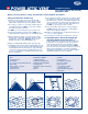


Ridge Line
M
e
as
u
r
e
Interior
Rafters
15” (381 mm) or
17” (432 mm) diameter
24” (609 mm)
15” (381 mm) or
17” (432 mm) diameter
Ridge Line
M
e
as
u
r
e
Interior
Rafters
15” (381 mm) or
17” (432 mm) diameter
24” (609 mm)
15” (381 mm) or
17” (432 mm) diameter
Ridge Line
M
e
as
u
r
e
Interior
Rafters
15” (381 mm) or
17” (432 mm) diameter
24” (609 mm)
15” (381 mm) or
17” (432 mm) diameter
Ridge Line
M
e
as
u
r
e
Interior
Rafters
15” (381 mm) or
17” (432 mm) diameter
24” (609 mm)
15” (381 mm) or
17” (432 mm) diameter
Ridge Line
M
e
as
u
r
e
Interior
Rafters
15” (381 mm) or
17” (432 mm) diameter
24” (609 mm)
15” (381 mm) or
17” (432 mm) diameter
Ridge Line
M
e
as
u
r
e
Interior
Rafters
15” (381 mm) or
17” (432 mm) diameter
24” (609 mm)
15” (381 mm) or
17” (432 mm) diameter
Ridge Line
M
e
as
u
r
e
Interior
Rafters
15” (381 mm) or
17” (432 mm) diameter
24” (609 mm)
15” (381 mm) or
17” (432 mm) diameter
Ridge Line
M
e
as
u
r
e
Interior
Rafters
15” (381 mm) or
17” (432 mm) diameter
24” (609 mm)
15” (381 mm) or
17” (432 mm) diameter
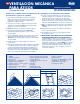
Figure 1a
Figure 1b
Figure 1c
Figure 2a
Figure 3a
Figure 3b
Figure 2cFigure 2b
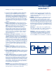
POWER ATTIC VENT
Installation Instructions
For Roof-Mount Models: PR1, PR2, PR3,
ERV4, ERV5 & ERV6
Roof Mount
Always read and observe safety considerations and installation instructions.
Tools Required
Safety Considerations & Warnings
1. Use this unit only in the manner intended by GAF.
If you have any installation questions, please contact
Master Flow
®
Technical Services at 1-800-211-9612.
2. For rooftop or outdoor use only. This ventilator has an
unguarded impeller. Do NOT use in locations readily
accessible to people or animals.
3. Do NOT use on roofs having a slope less than 2:12.
4. For general ventilation purpose only. Do NOT use to
exhaust hazardous material, dust, or combustible vapors.
5. During installation, always wear appropriate safety
glasses, gloves, hard hats, restraints, and other safety
equipment to avoid injury. Warning: Always wear
durable work gloves when handling this unit.
6. Observe all applicable building and electrical codes.
7. Installation work and electrical wiring should be done by
a qualified person in accordance with all building codes
and the National Electrical Code (U.S. only), including
codes for fire ratings. Contact a qualified electrician if
you are not comfortable or familiar with electrical codes
and/or installations.
8. The ventilator should be connected to a 120 volt, 60 Hz
grounded circuit only with minimum 14-gauge wiring
that has at least 3 amperes of available capacity. If you
cannot confirm there is sufficient electrical capacity on
an existing circuit, install a separate dedicated circuit.
Do NOT use an extension cord to operate.
9. Inspect for hidden utilities before cutting or drilling.
Do NOT damage electrical wiring or other hidden
utilities when cutting or drilling.
10. Make sure the fan blade is on tight and ensure the set
screw is securely tightened.
11. Ducted fans must always be vented to the outdoors.
12. FOR HOMES WITH A GAS OR OIL FURNACE OR
APPLIANCE LOCATED IN THE SAME SPACE: The
ventilator MUST be wired with a switch or other inter-
locking device to prevent the furnace and ventilator
from operating at the same time during the heating
cycle. The switch or other interlocking device MUST
disconnect the vent unit from the electrical circuit power.
GAF recommends that the switch (not included) be
installed by a qualified person in accordance with all
applicable building codes and standards.
• Drill
• Extension Cord
•
1
/
8
" Drill Bit
•
7
/
16
" Socket or Adjustable Wrench
• Utility Knife
• Power Saber or Jig Saw
and Hand Saw
• Safety Eyewear
• Hard Hat and Other
Safety Equipment
• Fall Restraint Equipment
• Galvanized Roofing Nails
• Caulking Gun
• Urethane Sealant or Roofing
Cement
• Gloves
• Ladder
• Claw Hammer
• Flat Blade Screwdriver
• Pencil or Marker
• Tape Measure
•
1
/
2
" Trade Size Cable
Clamp Connector
• Type NM Electrical Cable
• Wire Nuts
V971381©2015 GAF 3/15 1 Campus Drive, Parsippany, NJ 07054