ITEM #0006554 5-BURNER GAS GRILL MODEL #3218LTN R ○ Master Forge & M Design® is a registered trademark of LF, LLC. All rights reserved. Español p. 53 WARNING Improper installation, adjustment, alteration, service or maintenance can cause injury or property damage. Read this instruction manual thoroughly before installing or servicing this equipment. WARNING 1. Do not store or use gasoline or other flammable vapors and liquids in the vicinity of this or any other appliance. 2.
TABLE OF CONTENTS Safety Information ................................................................................................................3 Safety Tips……………………………………………………………………………………………5 Package Contents .................................................................................................................6 Hardware Contents ...............................................................................................................8 Preparation .....................................
SAFETY INFORMATION Please read and understand this entire manual before attempting to assemble, operate or install the product. If you have any questions regarding the product, please call customer service at 1-800-963-0211, 8:00 am to 6:00 pm, EST, Monday- Thursday, 8:00 a.m. to 5:00 p.m., EST, Friday. 1 The installation of this appliance must conform with local codes or, in the absence of local codes, with either the National Fuel Gas Code, ANSI Z223.
SAFETY INFORMATION 15 The pressure regulator for LP-gas grill is set for 11-in. water column (WC). Natural gas grill provides a hose assembly which includes a quick-disconnect device. But no pressure regulator. The LP pressure regulator or the Natural gas hose assembly must be used. Replacement pressure regulators and hose assemblies must be those specified in the part list. 16 The cylinder used must include a collar to protect the cylinder valve.
SAFETY TIPS Never pull your grill. Always push it. Never move your grill while it is in operation or still hot. Always use a protected hand when cleaning the grid surface after the post-heating period and when closing the propane tank valve. Use a covered hand during the grilling period. Wait until the burner box has completely cooled before reaching under to turn off the gas.
PACKAGE CONTENTS 6 Lowes.
PACKAGE CONTENTS Part Description Quantity Part Description Quantity A Burner Box 1 Q Locking Caster 2 B Heat Tent 5 R Transformer 1 C Main Grid 3 S Main Bottom Panel 1 D Warming Rack 1 T Caster 2 E Sear Burner Grid 1 U Right Door 1 F Sear Burner Drip Tray 1 V Right Skirt 1 G Grill Handle 1 W Main Beam 1 H Battery 5 X Center Door 1 I Left Rear Panel 1 Y Left Door 1 J Right Rear Panel 1 Z Left Skirt 1 K Center Panel 1 AB Left Panel 1 L
HARDWARE CONTENTS AA BB 1/4-20 x 5/8 in. Screw Qty. 57 Nut Qty. 2 CC 5/32-32 x 3/8 in. Screw Qty. 6 DD EE Flat Head 5/32-32 x 1/2 in. Screw Qty. 8 3/16-24 x 1/2 in. Screw Qty. 4 FF Wrench Qty. 1 PREPARATION Before beginning assembly of product, make sure all parts are present. Compare parts with package contents list and diagram above. If any part is missing or damaged, do not attempt to assemble the product. Contact customer service for replacement parts.
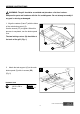
ASSEMBLY INSTRUCTIONS WARNING: The grill should be assembled and placed on a flat level surface. Compare the parts and hardware with the list and diagrams. Do not attempt assembly if any part is missing or damaged. 1. Align the casters (Q and T) with the holes 1 of the main bottom panel (S). Q Use the wrench (FF) to tighten. When this process is completed, turn the bottom panel over. The two locking casters (Q) should be at the back of the grill. (Fig. 1) T S 2.
ASSEMBLY INSTRUCTIONS 3. Align the holes in the left rear panel (I) with the holes in the main bottom panel (S) and 3 I insert the screws (BB) into the aligned holes. (Fig. 3) BB Hardware Used BB 1/4-20 x 5/8 in. Screw X4 S Note: Do not tighten the screws completely. Leave at least one full turn on each. After all the screws have been installed, go back and tighten them fully. 4.
ASSEMBLY INSTRUCTIONS 5. Align the holes in the Center Panel (K) 5 with the holes in the main bottom panel (S) K and insert the screws (BB) into the aligned holes and tighten them. (Fig. 5) Note: Do not tighten the screws completely. Leave at least one full turn on each. Hardware Used BB 1/4-20 x 5/8 in. Screw X3 S 6. For right rear panel (J), there are four screws (BB) to connect to the left rear panel (I) and main bottom panel (S), three in the rear and one inside the cabinet.
ASSEMBLY INSTRUCTIONS 7. Slide the tank ring bracket (M) to the end of the patented safety tank ring (AC) as shown. 7 AC BB Then align the holes in the ring bracket with left rear panel (I), insert screws (BB) into the holes from outside of grill, and then tighten completely. (Fig. 7) I Hardware Used BB 1/4-20 x 5/8 in. Screw X2 M 8. For the door magnet (L), there are four screws (CC) to connect to the center panel (K). Insert the screws into the aligned holes and tighten them. (Fig.
ASSEMBLY INSTRUCTIONS 9. For right panel (P), there are six screws (BB) to connect to the right rear panel (J) and the main bottom panel (S), three in the rear and three inside the cabinet. Insert the screws into the aligned holes and tighten them. The three screws inside the cabinet should be engaged first. (Fig. 9) 9 J P Hardware Used BB 1/4-20 x 5/8 in. Screw X6 S 10. For shelf board (N), there are four screws (BB) to connect to the center panel (K) and the right panel (P).
ASSEMBLY INSTRUCTIONS 11. For left skirt (Z), there are four screws (BB) to connect to the left panel (AB) and main bottom 11 Tab A panel (S), two in the left panel and two inside the cabinet. Make sure the tab A is locked in place. Insert the screws into the aligned holes and tighten BB them. The two screws inside the cabinet should be AB Z engaged first. (Fig. 11) Hardware Used BB 12. 1/4-20 x 5/8 in.
ASSEMBLY INSTRUCTIONS 13. Align the holes in the hinges of the two 13 doors (X and Y) with the two skirts (V and Z), DD insert flat head screws (DD) into the holes, and then tighten. (Fig. 13) Hardware Used Flat Head 5/32-32 x 1/2 in. Screw DD X8 V X Y 14. Z Align the holes in the main beam (W) with side panels (P and AB) and two skirts 14 BB (V and Z), insert screws (BB) into the holes, and then tighten. There are four screws to connect the side panels and two screws to connect the skirts.
ASSEMBLY INSTRUCTIONS 15. For right door (U), insert bottom hinge pin into hole in the main bottom panel (S). 15 K Push down on top hinge pin to insert into W hole on the main beam (W). Loosen the screws holding the magnets to center panel (K). Adjust magnets to contact the right door, then tighten the screws again. (Fig. 15) U S 16. Align the holes in the drip tray support 16 (AE) with the holes in the main beam (W) BB and in the left rear panel (I).
ASSEMBLY INSTRUCTIONS 17. Slide the main burner drip tray (AF) 17 between the drip tray support (AE) from AE the back of grill. (Fig. 17) AF 18. Attach the battery box (AG) to the left 18 panel (AB) with screws (CC) and nuts (AA). (Fig. 18) AG CC AA Hardware Used CC 5/32-32 x 3/8 in. Screw X2 AA Nut X2 AB 17 Lowes.
ASSEMBLY INSTRUCTIONS 19. Take the pressure regulator out from under 19 A the burner box (A). Then lift the burner box (A) onto the cabinet, making sure that the gas pressure regulator is in the cabinet, then position Tab burner box on the cabinet by aligning the four tabs on top of the cabinet with the holes in the burner box. Fasten the burner box to the cabinet with 4 screws (BB). (Fig. 19) BB Hardware Used 1/4-20 x 5/8 in. Screw BB 20.
ASSEMBLY INSTRUCTIONS 21. Connect the connector which is on the end 21 of the light wire from step 20 to the transformer (R). I Push the connector to mate firmly with the transformer. Then, screw and tighten the cap on the connector. (Fig. 21) R connector 22. On the NG model, pass the natural 22 I gas hose through the hole in the left rear panel (I) to your gas supply system. (Fig. 22) NG hose 23.
ASSEMBLY INSTRUCTIONS 24. Loosen the eight screws in the side panel of burner box and the bottom panel 24 three turns. This will allow for quick assembly of the buffet table. (Fig. 24) 25. Align the holes of the hinges in the 25 buffet table (AD) with the holes in the burner AD box and the main bottom panel. Tighten the eight screws loosened during step 24. (Fig. 25) 20 Lowes.
ASSEMBLY INSTRUCTIONS 26. Slide the sear burner drip tray (F) from 26 the back of burner box (A) to the sear burner bracket. (Fig. 26) A F Sear burner bracket 27. Put a battery (H) into the electronic 27 ignition with correct pole direction. (Please refer to the battery mark on the side of the cap). Push and turn the knobs to check if there are sparks produced between the ignition pin and the main burner. If not, please refer to the troubleshooting section to solve the problem. H (Fig.
ASSEMBLY INSTRUCTIONS 28. Connect the joint of the battery box (AG) 28 with the joint of the LED light wire. (Fig. 28) Note: 4 batteries included in the package must be put into the battery box. AB Joint 29. AG Position the sear burner grid (E), 5 heat tents (B), 3 main grids (C), 29 D E and 1 warming rack (D) into place. (Fig. 29) C B 22 Lowes.
ASSEMBLY INSTRUCTIONS IMPORTANT CHECK SPARKS After you complete your grill assembly, test your ignition system with the GAS OFF. Check for continuous sparks when pushing in the knob ignition system. For the side burner, sparks can be seen directly. For main burners, the ignition system is positioned next to each burner inside the burner box. A reflection of sparks or sparks can be seen at the front of the inside of the burner box.
COOKING WITH GAS For Portable LP-Gas Connection The cabinet has an opening in the bottom panel that allows a 20 lb. gas tank bottom flange to drop into place (tank sold separately). This will help to lock the tank in place. Before installing your gas tank, lift up the patented safety tank ring (as shown in Fig. 29a). After positioning the tank in the opening, lower the patented safety tank ring to lock the tank. Use only 20 lb. gas tank (see LP Gas Safety Requirements for Additional Information).
COOKING WITH GAS a. Hand Assembly: 1. Make certain the tank valve and all the appliance valves are in the “OFF” positions. 2. When connecting the regulator/burner valve assembly to the tank valve, turn the large plastic nut clockwise until it stops. 3. Gas will not flow unless the plastic nut is completely connected. 4. HAND TIGHTEN ONLY. b. Hand Disassembly: 1. Make certain the tank valve and all the appliance valves are in the “OFF” positions. 2.
COOKING WITH GAS For Natural Gas Connection Preparing: 1. Turn off gas supply, and then remove cap on gas supply side. 2. Recommended: Install a shut-off valve on gas supply side before installing the socket. 3. Socket should be installed by an authorized technician in accordance with the national fuel gas code (NFPA 54/ANSI223.1). 4. Before inserting plug, turn on gas supply and leak test all connections including the stem of the shut-off valve and the opening of the socket.
COOKING WITH GAS LP Gas If your grill is for LP Gas, the regulator supplied is set for an 11-in. water column (WC) and is for use with LP gas only. The factory-supplied regulator and hose must be used with a 20-lb. LP gas tank. Natural Gas Your grill 3218LTN is natural gas convertible. NG kit sold separately (Item #0050772). Please follow the manual to convert your grill to natural gas. If your grill is for Natural Gas, it is set for a 7-in. water column (WC) and is for use with Natural Gas only.
COOKING WITH GAS (c) Provided with a tank connection device compatible with the connection for outdoor cooking appliances. The tank should be 12 inches in diameter and 18-1/2 inches tall and be equipped with a Type-1 fitting. The tank supply system must be arranged for vapor withdrawal. The tank used must include a collar to protect the cylinder valve. Do not operate the gas grill indoors or in any enclosed area. If the gas grill is not in use, the gas must be turned off at the supply tank.
COOKING WITH GAS When transporting the tank to your local propane gas dealer, make sure the valve is closed tightly and the protective cover is in place. Position the tank securely in an upright position so it will not roll around your vehicle. If you plan to make stops for shopping or errands, have your liquid propane tank filled at the last stop before going home. Again, make certain the refilled tank is secure and in an upright position. When you return home, remove the refilled tank from your vehicle.
COOKING WITH GAS The proper way to fill a tank is by weight. The empty tank should be placed on a scale. The scale weights should be readjusted to a weight that would allow up to 80% of the total weight. The filling operation must end once the tank is filled to 80% of its total capacity. If the tank is not completely empty, the scale readjustment must be changed to consider the propane (LP) already in the tank.
OPERATING INSTRUCTIONS Grill Lighting Instructions Checking orifices' alignment with burners Orifices may shift during assembly and movement; therefore, check the orifices' alignment with the burners according to the following illustrations before lighting. Orifice stud inside the air shutter Fig. 34 Main Burner and Orifice Relationship Fig. 35 Sear Burner and Orifice Relationship Lighting Instructions 1. Read instructions before lighting your grill. 2. Open lid during lighting. 3.
OPERATING INSTRUCTIONS WARNING: 1. Make sure the hood is completely open each time you attempt to light the grill. Failure to open the hood could lead to delayed ignition resulting in bodily harm. For the side sear burner, do not use ANYTIME with lid in the down position. 2. This grill is equipped with a flame-observation hole in side panel. Wear protective mitts before using the flame watch. CAUTION: It is important to inspect the full length of the gas line hose.
OPERATING INSTRUCTIONS Fig. 37 Match/Paper Lighting Illustration Breaking in Your Grill When firing your grill for the first time, it is advisable to run the main burner(s) on “HIGH” for 20 minutes with the hood down and then turn the main burners off. This tempers the grill. For the side sear burner, do not use ANYTIME with lid in the down position. Preheating Grill It is extremely important that your grill be up to temperature before you begin using it.
OPERATING INSTRUCTIONS We recommend always cooking with the lid CLOSED if you are in a windy area or colder climate. Your 3218LTN Grill has been designed and constructed to give you maximum flexibility and cooking performance. Be creative. Try different cooking methods on your grill to determine which suits your needs best. There is no right or wrong way to cook, just different cooking styles. Get creative and enjoy! WARNING: Please remember this is an outdoor gas grill.
OPERATING INSTRUCTIONS FOLD OUT BUFFET TABLE INSTRUCTION The grill has a patented fold out buffet table which can be retracted when not in use. (Fig. 38) 38 Buffet table To fold out the buffet table, follow the steps below: 39 1. Pull the bottom of the table and bring it out. (Fig. 39) 2. Hold the table top while lifting up the table. During this process, pay attention to hold the table top to prevent it from dropping down. (Fig. 40) 35 40 Lowes.
OPERATING INSTRUCTIONS 3. The table will be locked where the table supports are nearly in line. You can hear a sound click when they are fixed. (Fig. 41) To fold down the buffet table, follow the steps below: 41 42 4. Pull the handle under the table. (Fig. 42) Handle 36 Lowes.
OPERATING INSTRUCTIONS 5. Hold the table and bring it down slowly. (Fig. 43) 43 6. Push the table to the vertical position. (Fig. 44) 37 44 Lowes.
CARE AND MAINTENANCE Transformer Connection Instruction For your safety the 3218LTN grill comes equipped with a UL approved transformer for outdoor use that provides low voltage to power a 10-watt grill light featured with this model. Fig. 45 All wiring is factory connected except the easy connection you must make: connect the factory wire to the transformer with a provided screw-on plastic connector.
CARE AND MAINTENANCE Light Operation Instruction 1. Make sure light’s power switch on the control panel is in the “OFF” position. 2. Connect power plug to properly grounded outlet. 3. Turn the light’s power switch to “ON”. WARNING Keep any electrical supply cord away from any heated surface. Do not turn on the lights when the hood is closed.
CARE AND MAINTENANCE 3. Remove the lamp screen. (Fig. 48) 48 Lamp screen 4. Pull out the light bulb and replace with a new bulb. (Fig. 49) 49 Bulb 5. Reverse the instruction from “steps” 4-1 for installation. Cleaning Method Follow Steps 1-3 above for glass cover removal. Use a damp towel to clean the surface of glass cover. Make sure the glass cover is completely dry before re-installing.
CARE AND MAINTENANCE Bulb specification Bulb Type: Halogen Wattage: 10 watts per bulb Voltage: 12 volts Please contact customer service at 1-800-963-0211 for assistance on bulb replacement information. Checking the Flame Refer to Fig. 50 below (side view of grill). Check the flame after the grill is lit. Make sure you have a stable mostly blue flame. Flame Observation Hole and Slots Fig. 50 Air Shutter Adjustment The main burner shutters are adjusted at the factory for your convenience.
CARE AND MAINTENANCE (a) Air Shutter (b) (c) Fig. 51 Air Shutter Fig. 52 Acceptable Flame (only a) CAUTION: If the natural gas conversion kit is used, remember to adjust the air shutter of main burner (for details, please read the manual of NG conversion). Replacing the Battery 1. Unscrew the cap on the battery compartment and remove the old battery. 2. Replace with a new battery and re-install the cap. Note: The negative (-) side of the battery goes in first.
CARE AND MAINTENANCE Do not use abrasive cleaners on the polished surface. Use caution when cleaning. Metal polish or a mild chrome cleaner can be used to bring back luster and highlights. Rust remover can be used to remove rust stains that occur from outside sources. Follow the rust removal instructions carefully. To touch up minor scratches in the stainless steel, sand the affected surface lightly with 160 dry grit emery sand paper in the direction of the grain.
CARE AND MAINTENANCE Helpful Care and Maintenance Hints Before grilling, pre-heat grill for 15 minutes on "HIGH" with hood down. To avoid uncontrolled flare-ups or grease fires, grill meats with hood open. Close hood if meats are thick or weather is cold, or if you are using a rotisserie or indirect cooking. For the side sear burner, do not use ANYTIME with lid in the down position. Always protect your hand with a pot holder or cooking glove when coming into contact with a hot surface.
CARE AND MAINTENANCE WARNING: 1. To protect against electric shock, do not immerse cord or plugs in water or other liquid; 2. Unplug from the outlet when not in use and before cleaning. Allow to cool before putting on or taking off parts; 3. Do not operate any outdoor cooking gas appliance with a damaged cord, plug, or after the appliance malfunctions or has been damaged in any manner. Contact the manufacturer for repair; 4. Do not let the cord hang over the edge of a table or touch hot surfaces; 5.
TROUBLESHOOTING Problem Possible Cause Corrective Action 1. The ignition wire came off the electrical igniter. 2. The distance between the ignition pin and the burner is greater than 0.1-0.2 inch (side burner). 3. The ignition wire is broken. Grill or side cooker will not light. Burner flame is yellow and gas odor can be smelled. 3. Call customer service for a replacement ignition wire. 4. Install a new AA battery. 5. Change the battery polarity. 4. The battery has died. 5. The battery is in the 6.
TROUBLESHOOTING Problem Possible Cause Corrective Action Check your gas line and make corrections by following the chart below. From House to Grill Low heat, natural gas. Gas pressure is significantly affected by gas line and length of gas line from house gas line. Distance Up to 25 ft. 3/8 in. diameter 26 -50 ft. 51 -100 ft. Low heat, LP gas. Tubing Size 1/2 in. diameter 1/3 in. of run 1/2 in. 2/3 in. of run 3/4 in.
TROUBLESHOOTING 1. Out of gas. 2. Excess flow valve tripped. Sudden drop in gas flow or low flame. Cooking light will not turn on. LED control panel lights do not light up. 3. Vapor lock at coupling nut/LP cylinder connection. 1. No power supply. 2. Defective Halogen bulb. 3. Internal wiring issue. 1. No power supply. 2. Damaged wiring or loose connection. 3. Wiring not attached to control panel switch. 4. Defective switch. 5. Defective LED’s. 48 1. Check for gas in LP cylinder. 2.
WARRANTY Proof of purchase is required to access this warranty program, which is in effect from the date of purchase. Customers will be subject to parts, shipping, and handling fees if unable to provide proof of purchase or after the warranty has expired. Before returning to your retailer, call our customer service department at 1-800-963-0211, 8:00 a.m. to 6:00 p.m., EST, Monday-Thursday, 8:00 a.m. to 5:00 p.m., EST, Friday. Limited Warranty 5-Year Warranty on stainless steel burners.
REPLACEMENT PARTS LIST For replacement parts, call our customer service department at 1-800-963-0211, 8:00 a.m. to 6:00 p.m., EST, Monday- Thursday, 8:00 a.m. to 5:00 p.m., EST, Friday. 50 Lowes.
REPLACEMENT PARTS LIST Part Description Part # Description Part # 1 HEAT TENT L3218-00-2001 39 MAIN BURNER KNOB E3518-00-3001 2 COOKING GRID 3218LT-00-2010 40 SWITCH E3520-00-8015 3 WARMING RACK L3218-00-2020 41 PANEL LIGHT WIRE 3218LT-00-8013 4 HOOD HANDLE 3218LT-00-4300 42 BATTERY BOX 3218LT-00-8014 5 HOOD HANDLE BASE 3218LT-00-4005 43 REAR BURNER KNOB L3218-00-3001 6 TEMPERATURE GAUGE 2518-3-8012 44 REAR BURNER KNOB BEZEL L3218-00-3002 7 TEMPERATURE GAUGE BEZEL
REPLACEMENT PARTS LIST Part Description Part # Description Part # S1 PIN SHAFT GB 882 6×35 S7 SELF-TAPPING SCREW ST3.5×9.5 S2 SCREW 1/4-20 × 5/8" S8 R PIN R PIN S3 SCREW 3/16-24 x 1/2" S9 SCREW AND NUT 5/16-18UNC x 1" S4 SCREW 5/32-32 x 3/8" S10 SCREW 1/4-20 × 7/8" S5 SCREW M4 × 8 S11 PIN GB/T 91 1.6×10 S6 FLAT HEAD SCREW 5/32-32 x 1/2" Part Printed in China Master Forge & M Design® is a registered trademark of LF, LLC. All rights reserved. 52 Lowes.
ARTÍCULO #0006554 PARRILLA A GAS DE 5 QUEMADORES R ○ MODEL #3218LTN Master Forge & M Design® es una marca registrada de LF, LLC. Todos los derechos reservados. ADVERTENCIA La instalación, ajuste, alteración, reparación o mantenimiento inadecuados pueden ocasionar lesiones o daños a la propiedad. Lea detenidamente este manual de instrucciones antes de instalar o reparar este equipo. ADVERTENCIA 1.
TABLA DE CONTENIDO Información de seguridad ...................................................................................................55 Consejos de seguridad .……….……………………………………...………………………….57 Contenido del paquete ........................................................................................................68 Aditamentos .........................................................................................................................60 Preparación ..............................
INFORMACIÓN DE SEGURIDAD Lea y comprenda completamente este manual antes de intentar ensamblar, usar o instalar el producto. Si tiene preguntas relacionadas con el producto, llame a nuestro Departamento de Servicio al Cliente al 1-800-963-0211, de lunes a jueves de 8:00 a.m. a 6:00 p.m., y los viernes de 8:00 a.m. a 5:00 p.m., hora estándar del Este. 1 La instalación de este electrodoméstico debe cumplir con los códigos locales o, en su defecto, con el Código nacional de gas combustible, ANSI Z223.
INFORMACIÓN DE SEGURIDAD 16 El cilindro usado debe incluir un anillo para proteger su válvula. 17 No almacene un cilindro de gas PL de reserva debajo o cerca de este electrodoméstico. 18 Nunca llene el cilindro a más del 80% de su capacidad. 19 Si no se sigue con precisión la información detallada en los puntos “17” y “18”, se podría producir un incendio que podría ocasionar lesiones graves o la muerte.
CONSEJOS DE SEGURIDAD Nunca arrastre la parrilla. Empújela. Nunca mueva la parrilla mientras está en funcionamiento o si aún está caliente. Use siempre guantes de protección cuando limpie la superficie de la rejilla después del período de post calentamiento y cuando cierre la válvula del tanque de propano. Use protección en las manos durante el asado de alimentos. Espere hasta que la caja del quemador se haya enfriado completamente antes de cerrar el paso del gas.
CONTENIDO DEL PAQUETE 58 Lowes.
CONTENIDO DEL PAQUETE Pieza Descripción Cantidad Pieza Descripción Cantidad A Caja del quemador 1 Q Rueda con seguro 2 B Cámara de calor 5 R Transformador 1 C Parrilla principal 3 S Panel inferior principal 1 D Parrilla para calentar 1 T Rueda 2 1 U Puerta derecha 1 1 V Faldón derecho 1 E F Parrilla del quemador para asar Quemador para asar Bandeja para líquidos G Manija de la parrilla 1 W Viga principal 1 H Batería 5 X Puerta central 1 1 Y Puerta izqui
ADITAMENTOS AA BB Tuerca Cant. 2 Tornillo 1/4-20 x 5/8” Cant. 57 CC Tornillo 5/32-32 x 3/8” Cant. 6 DD Tornillo de cabeza plana 5/32-32 x 1/2” Cant. 8 EE Tornillo 3/16-24 x 1/2” Cant. 4 FF Llave Cant. 1 PREPARACIÓN Antes de comenzar a ensamblar el producto, asegúrese de tener todas las piezas. Compare las piezas con la lista del contenido del paquete y el diagrama anterior. No intente ensamblar el producto si falta alguna pieza o si éstas están dañadas.
INSTRUCCIONES DE ENSAMBLAJE ADVERTENCIA: La parrilla debe ser ensamblada y colocada sobre una superficie plana y nivelada. Compare las piezas y los aditamentos con la lista y diagramas. No intente ensamblar el producto si faltan piezas o si éstas están dañadas. 1. Alinee las ruedas (Q y T) con los orificios 1 en el panel inferior principal (S). Use la llave de Q tuercas (FF) para apretar. Una vez completado dicho proceso, dé vuelta el panel inferior.
INSTRUCCIONES DE ENSAMBLAJE 3. Alinee los orificios en el panel posterior 3 izquierdo (I) con los orificios en el panel I inferior principal (S) e inserte los tornillos (BB) en los orificios alineados. (Fig. 3) BB Aditamentos utilizados BB Tornillo 1/4-20 x 5/8" X4 S Nota: No ajuste los tornillos por completo. Deje al menos una vuelta completa en cada uno. Una vez instalados todos los tornillos, ajústelos completamente. 4.
INSTRUCCIONES DE ENSAMBLAJE 5. Alinee los orificios en el panel central (K) con los orificios en el panel inferior principal (S) e inserte los tornillos (BB) en los orificios alineados y apriételos. (Fig. 5) 5 K Nota: No apriete completamente los tornillos. Deje al menos una vuelta completa en cada uno. Aditamentos utilizados BB Tornillo 1/4-20 x 5/8” S X3 6.
INSTRUCCIONES DE ENSAMBLAJE 7. Deslice la abrazadera del anillo del tanque (M) hacia el extremo del anillo de seguridad patentado del tanque (AC) como se muestra. Luego, alinee los orificios en la abrazadera del anillo con el panel posterior izquierdo (I), inserte los tornillos (BB) en los orificios desde la parte exterior de la parrilla y apriételos completamente. (Fig. 7) 7 AC BB I Aditamentos utilizados BB Tornillo 1/4-20 x 5/8” X2 M 8.
INSTRUCCIONES DE ENSAMBLAJE 9. Hay seis tornillos (BB) para conectar el panel derecho (P) al panel posterior derecho (J) y el panel inferior principal (S): tres en la parte posterior y tres dentro del gabinete. Inserte los tornillos en los orificios alineados y apriételos. Primero debe colocar los tres tornillos dentro del gabinete. (Fig. 9) 9 J P Aditamentos utilizados BB Tornillo1/4-20 x 5/8” X6 S 10.
INSTRUCCIONES DE ENSAMBLAJE 11. Hay cuatro tornillos (BB) para conectar el faldón izquierdo (Z) al panel izquierdo (AB) y el panel inferior principal (S): dos en el panel izquierdo y dos dentro del gabinete. Asegúrese de que la lengüeta A esté bien segura en su lugar. Inserte los tornillos en los orificios alineados y apriételos. Primero debe colocar los dos tornillos dentro del gabinete. (Fig. 11) 11 Lengüeta A BB AB Z Aditamentos utilizados BB Tornillo 1/4-20 x 5/8” S X4 12.
INSTRUCCIONES DE ENSAMBLAJE 13. Alinee los orificios en las bisagras de 13 las dos puertas (X e Y) con los dos faldones DD (V y Z), inserte los tornillos de cabeza plana (DD) en los orificios y apriételos. (Fig. 13) Aditamentos utilizados DD Tornillo de cabeza plana 5/32-32 x 1/2” X8 V X Y 14. Alinee los orificios de la viga principal Z 14 BB (W) con los paneles laterales (P y AB) y los dos faldones (V y Z), inserte los tornillos (BB) en los orificios y apriételos.
INSTRUCCIONES DE ENSAMBLAJE 15. En la puerta derecha (U), inserte el 15 pasador de la bisagra inferior en el orificio K del panel inferior principal (S). Presione el W pasador de bisagra superior para insertarlo en el orificio de la viga principal (W). Afloje los tornillos que sostienen los imanes en el panel central (K). Ajuste los imanes para que entren en contacto con la puerta U derecha, luego apriete los tornillos de nuevo. (Fig. 15) S 16.
INSTRUCCIONES DE ENSAMBLAJE 17. Deslice la bandeja de goteo del 17 quemador principal (AF) entre el soporte AE de la bandeja de goteo (AE) desde la parte posterior de la parrilla. (Fig. 17) AF 18. Fije la caja de baterías (AG) al panel 18 izquierdo (AB) con tornillos (CC) y tuercas (AA). (Fig. 18) AG CC AA Aditamentos utilizados CC Tornillo 5/32-32 x 3/8” X2 AA Tuerca X2 AB 69 Lowes.
INSTRUCCIONES DE ENSAMBLAJE 19. Retire el regulador de presión ubicado 19 debajo de la caja del quemador (A). Luego, A levante la caja del quemador (A) y colóquela Lengüet sobre el gabinete, asegurándose de que el regulador de presión de gas se encuentre en el gabinete, luego, coloque la caja del quemador sobre el gabinete alineando las cuatro lengüetas de la parte superior del gabinete con los orificios en la caja del BB quemador. Fije la caja del quemador al gabinete con 4 tornillos (BB). (Fig.
INSTRUCCIONES DE ENSAMBLAJE 21. Conecte el conector ubicado en el extremo del cable de la lámpara del paso 20 al 21 I transformador (R). Presione el conector para conectarlo firmemente al transformador. Luego, atornille y apriete la tapa del conector. (Fig. 21) R conector 22. En el modelo para gas natural, pase la 22 manguera de gas natural a través del orificio I en el panel posterior izquierdo (I) hacia el sistema de suministro de gas. (Fig. 22) La manguera de gas natural 23.
INSTRUCCIONES DE ENSAMBLAJE 24. Afloje los ocho tornillos fijados en el panel 24 lateral de la caja del quemador y en el panel posterior 3 vueltas. Esto permitirá ensamblar rápidamente la mesa para aparador. (Fig. 24) 25. Alinee los orificios de las bisagras en la 25 mesa para aparador (AD) con los orificios en AD la caja del quemador y el panel inferior principal. Apriete los ocho tornillos que aflojó en el paso 24. (Fig. 25) 72 Lowes.
INSTRUCCIONES DE ENSAMBLAJE 26. Deslice la bandeja de goteo del quemador 26 para asar (F) desde la parte posterior de la caja del quemador (A) hasta la abrazadera del quemador para asar. (Fig. 26) A F Soporte de la hornilla para dorar 27. Coloque una batería (H) en el encendido electrónico con sus polos en la dirección correcta. 27 (Consulte las indicaciones de la batería en el costado de la tapa).
INSTRUCCIONES DE ENSAMBLAJE 28. Conecte la unión de la caja de baterías 28 (AG) con la unión del cable de la lámpara LED. (Fig. 28) Nota: Inserte las 4 baterías que se incluyen en el paquete en la caja de baterías. AB Unión 29. Coloque la parrilla del quemador para 29 asar (E), 5 cámaras de calor (B), 3 parrillas D E principales (C) y 1 rejilla para calentar (D) en su lugar. (Fig. 29) C B 74 AG Lowes.
INSTRUCCIONES DE ENSAMBLAJE IMPORTANTE VERIFIQUE SI PRODUCE CHISPAS Una vez ensamblada la parrilla, pruebe el sistema de encendido con el GAS CERRADO (OFF). Verifique si produce chispas cuando presiona en el sistema de encendido de la perilla. En los quemadores laterales, las chispas pueden verse directamente. En los quemadores principales, el sistema de encendido está ubicado junto a cada quemador dentro de la caja del quemador.
COCINAR CON GAS Para la conexión de gas PL portátil El gabinete tiene una abertura en el panel inferior que permite colocar en el lugar una brida inferior para el tanque de gas de 9,07 kg (no se incluye el tanque). Esto ayudará a asegurar el tanque en su lugar. Antes de instalar el tanque de gas, levante el anillo de seguridad patentado del tanque (como se muestra en la Fig. 29a). Una vez colocado en tanque en la abertura, baje el anillo de seguridad patentado del tanque para asegurar el tanque.
COCINAR CON GAS a. Ensamblaje manual: 1. Asegúrese de que la válvula del tanque y todas las válvulas del electrodoméstico estén en la posición “OFF”. 2. Cuando conecte el ensamble de la válvula del quemador/regulador a la válvula del tanque, gire la tuerca de plástico grande en dirección de las manecillas del reloj hasta que se detenga. 3. El gas no fluirá a menos que la tuerca de plástico esté conectada completamente. 4. APRIETE A MANO SOLAMENTE. b. Desensamblaje manual: 1.
COCINAR CON GAS Importante: Antes de la utilización de un tanque de gas fresco, por favor, compruebe las fugas alrededor de las conexiones de acuerdo a la sección "Comprobación de Fugas de Gas, y asegúrese de que no haya fugas de vapor o la acumulación en el gabinete. Asegúrese de que todas las aberturas alrededor de las paredes laterales no están bloqueadas. Importante: Coloque la tapa para polvo en la salida de la válvula del cilindro cuando no esté en uso.
COCINAR CON GAS Para desconectar 1. Jale el manguito hacia atrás. Saque el tapón del socket. (El gas se corta automáticamente). 2. Cierre la válvula de cierre y reemplace las tapas para polvo en el socket y el tapón. Requisitos de gas La parrilla 3218LTN está establecida y revisada de fábrica para el tipo de suministro de gas a utilizarse. Identifique el tipo de gas, ya sea gas natural o gas PL, y asegúrese de que el etiquetado en la placa de clasificación concuerde con el suministro de gas indicado.
COCINAR CON GAS Tabla 1 BTU/HR Tipo de quemador 12000 x 5 Quemadores principales Quemador lateral Quemador para rostizar 12000 x 1 13000 x 1 Requisitos de seguridad del tanque de gas PL Para las parrillas a gas PL, el tanque de suministro de gas PL debe estar: (a) Fabricado y etiquetado según las especificaciones para tanques de gas PL del Departamento de Transporte de EE.UU.
COCINAR CON GAS Manipulación segura del tanque de propano líquido Recuerde manipular su tanque de propano líquido portátil con cuidado cuando lo lleve a su proveedor para que lo vuelva a llenar. Evite dejarlo caer o golpearlo contra objetos filosos. Los tanques de propano líquido están sólidamente fabricados, pero cualquier serie de sacudidas podría dañar el contenedor.
COCINAR CON GAS La forma correcta de llenar un tanque es según su peso. Se debe colocar el tanque vacío en una balanza. Se debe adaptar el peso de la balanza a un peso que permita llenar hasta el 80% del peso total. La operación de llenado debe finalizar una vez completado el 80% de la capacidad del tanque. Si el tanque no está completamente vacío, se debe cambiar la regulación de la balanza a fin de considerar el propano (PL) que se encuentra dentro del tanque.
INSTRUCCIONES DE FUNCIONAMIENTO Instrucciones de encendido de la parrilla Verificación de la alineación de los orificios con los quemadores Los orificios pueden moverse durante el ensamblaje y el traslado; por lo tanto, verifique la alineación de los orificios con los quemadores según las siguientes ilustraciones antes de encenderlos. Montante del orificio dentro del obturador de aire Fig. 34 Relación de los orificios con el quemador principal Fig.
INSTRUCCIONES DE FUNCIONAMIENTO ADVERTENCIA: 1. Asegúrese de que la cubierta esté abierta por completo cada vez que intente encender la parrilla. Si no abre la cubierta, podría retardar el encendido y ocasionar daños corporales. 2. Esta parrilla cuenta con un orificio por el que se pueden observar las llamas en el panel lateral. Utilice mitones de protección antes de usar la mira para las llamas. PRECAUCIÓN: Es importante inspeccionar el largo total de la manguera de la línea de gas.
INSTRUCCIONES DE FUNCIONAMIENTO Fig. 37 Ilustración del encendido con fósforo/papel Encendido inicial de la parrilla Cuando encienda la parrilla por primera vez, se recomienda que coloque los quemadores principales en “HIGH” durante 20 minutos con la cubierta abajo y que luego los apague. Esto atempera la parrilla. Precalentamiento de la parrilla Es muy importante que su parrilla tome temperatura antes de que comience a usarla.
INSTRUCCIONES DE FUNCIONAMIENTO Recomendamos que siempre cocine con la tapa CERRADA si se encuentra en una zona ventosa o de clima frío. La parrilla 3218LTN ha sido diseñada y fabricada para brindarle máxima flexibilidad y rendimiento de cocción. Sea creativo. Pruebe los diferentes métodos de cocción en su parrilla para determinar cuál satisface mejor sus necesidades. No existe una forma correcta o incorrecta de cocinar, simplemente diferentes estilos de cocción.
INSTRUCCIONES DE FUNCIONAMIENTO INSTRUCCIONES PARA EXTENDER LA MESA PARA APARADOR La parrilla cuenta con una mesa para aparador extensible patentada, la que se puede plegar cuando no se usa. (Fig. 38) 38 Mesa de buffet Para extender la mesa para aparador, siga los siguientes pasos: 39 1. Jale la parte inferior de la mesa hacia afuera. (Fig. 39) 2. Sostenga la cubierta de la mesa mientras levanta la mesa. Durante este proceso preocúpese de sostener la cubierta de la mesa para evitar que se caiga. (Fig.
INSTRUCCIONES DE FUNCIONAMIENTO 3. La mesa quedará fija en la posición donde los soportes de la mesa casi estén en línea. Escuchará un clic cuando estén fijos. (Fig. 41) Para plegar la mesa para aparador, siga los siguientes pasos: 41 42 4. Jale la manija bajo la mesa. (Fig. 42) Manejar 88 Lowes.
INSTRUCCIONES DE FUNCIONAMIENTO 5. Sostenga la mesa y bájela lentamente. (Fig. 43) 43 6. Empuje la mesa hasta dejarla en posición vertical. (Fig. 44) 44 89 Lowes.
LIMPIEZA Y MANTENIMIENTO Instrucciones para la conexión del transformador Para su seguridad, la parrilla 3218LTN está equipada con un transformador aprobado por UL para uso en exteriores, que brinda bajo voltaje para alimentar la lámpara de 10 vatios de la parrilla que se proporciona con este modelo. Fig. 45 Todo el cableado está conectado de fábrica, a excepción de esta fácil conexión que debe realizar usted: Conecte el cable de fábrica al transformador con el tornillo provisto en el conector de plástico.
LIMPIEZA Y MANTENIMIENTO Instrucciones de funcionamiento de la lámpara 1. Asegúrese de que el interruptor de alimentación de la lámpara que está en el panel de control se encuentre en la posición “OFF” (APAGADO). 2. Conecte el enchufe a un tomacorriente con la debida puesta a tierra. 3. Lleve el interruptor de alimentación de la luz a la posición “ON” (ENCENDIDO). ADVERTENCIA Mantenga todos los cables de suministro de electricidad alejados de cualquier superficie caliente.
LIMPIEZA Y MANTENIMIENTO 47 2. Utilice un destornillador para aflojar el tornillo que sujeta el panel posterior de la caja del quemador. Sostenga la pantalla de la lámpara durante este proceso; de lo contrario, puede caerse, romperse y producir lesiones personales. (Fig. 47) Lámpara de cristal Atornille aquí 3. Retire la pantalla de la lámpara. (Fig. 48) 48 Lámpara de cristal 49 4. Retire la bombilla y reemplácela por una nueva. (Fig. 49) Bombilla 5.
LIMPIEZA Y MANTENIMIENTO ADVERTENCIA La cubierta de vidrio de la lámpara no debe estar en contacto con el agua ni con otros líquidos cuando esté caliente. Un cambio brusco de temperatura puede ocasionar grietas en la cubierta de vidrio. ADVERTENCIA Para garantizar una protección continua contra descargas eléctricas: 1. Conecte sólo a tomacorrientes con la debida puesta a tierra. 2. No lo exponga a la lluvia. 3. Mantenga las conexiones de la extensión eléctrica secas y separadas del suelo.
LIMPIEZA Y MANTENIMIENTO ADVERTENCIA: No toque el quemador tras regularlo. El quemador está caliente. a. Afloje el obturador de aire. Los obturadores se encuentran al extremo de los quemadores de gas, debajo de la caja de control. Consulte la Fig. 51 b. Afloje el tornillo del obturador de aire. c. Encienda el quemador que desea regular. d.
LIMPIEZA Y MANTENIMIENTO Limpie todas las superficies no aptas para cocción con limpiador de acero inoxidable una vez al mes. Nunca limpie el acero inoxidable si está caliente. Después de asar por primera vez, algunas áreas de la parrilla (como los orificios de ventilación, la cubierta y la caja del quemador) pueden decolorarse. Se trata de una decoloración normal ocasionada por el intenso calor de los quemadores. Se pueden acumular y adherir motas de grasa en las superficies de acero inoxidable.
LIMPIEZA Y MANTENIMIENTO Arañas e insectos pueden anidar dentro de los quemadores de ésta o cualquier otra parrilla y ocasionar que el gas fluya desde la parte frontal del quemador. Esto podría ocasionar un incendio detrás del panel de la válvula que dañaría la parrilla y haría que su funcionamiento fuese inseguro. Inspeccione los quemadores al menos una vez al año o inmediatamente después de que ocurran las siguientes condiciones: 1. Se percibe olor a gas y las llamas del quemador son amarillas. 2.
LIMPIEZA Y MANTENIMIENTO Cuadro de tiempo de cuidado y mantenimiento Artículo de parrilla Superficie pintada Superficie de acero inoxidable Todas las rejillas Rejillas de acero inoxidable Rejillas de porcelana Cámaras de calor de quemadores Quemadores Frecuencia según el uso normal Dos veces al año Dos veces al año Después de cada uso 15 días Método de limpieza Cera para automóviles Limpiador para acero inoxidable Queme y limpie Apto para cepillo de alambre/lavaplatos 15 días Apto para frotar con agua j
SOLUCIÓN DE PROBLEMAS Problema Causa posible Acción correctiva La parrilla o la cocina lateral no encienden 1. El cable de encendido se desconectó del encendedor eléctrico. 2. La distancia entre el pasador de encendido y el quemador es superior a 2,60 mm-5,10 mm (quemador lateral). 3. El cable de encendido está roto. 4. La batería se ha agotado. 5. Los polos de la batería están mal colocados. 6. La punta del electrodo no produce chispas en el puerto del quemador. 7. No hay suministro de gas. 8.
SOLUCIÓN DE PROBLEMAS Problema El quemador se apaga Causa posible Acción correctiva 1. El tanque de PL está vacío. 2. El quemador no está alineado con la válvula de control. 3. El suministro de gas no es suficiente. 1. Vuelva a llenar el tanque de PL. 2. Instale el quemador correctamente. 3. Verifique la manguera de suministro de gas y asegúrese de que no haya fugas ni nudos. Verifique la línea de gas y realice las correcciones necesarias según la siguiente tabla.
SOLUCIÓN DE PROBLEMAS Problema Poco calor, gas PL Disminución repentina del flujo de gas o llama baja La luz de cocción no se enciende. Causa posible Acción correctiva El ensamble del regulador de propano cuenta con un dispositivo de control de flujo excesivo diseñado para suministrar suficiente flujo de gas a la parrilla. Los cambios bruscos en la presión pueden activar el dispositivo de control de flujo excesivo y producir una llama y temperatura bajas. 1. Se agotó el gas. 2.
GARANTÍA Se requiere un comprobante de compra para acceder a este programa de garantía, el cual entra en vigencia a contar de la fecha de compra. Si no se proporciona un comprobante de compra o una vez de que la garantía ha expirado, los clientes deberán pagar los cargos por piezas, envío y manipulación. Antes de volver a la tienda, llame a nuestro Departamento de Servicio al Cliente al 1-800-963-0211 de lunes a jueves de 8:00 a.m. a 6:00 p.m., y los viernes de 8:00 a.m. a 5:00 p.m., hora estándar del Este.
LISTA DE PIEZAS DE REPUESTO Para obtener piezas de repuesto, llame a nuestro Departamento de Servicio al Cliente al 1-800-963-0211, de lunes a jueves de 8:00 a.m. a 6:00 p.m., y los viernes de 8:00 a.m. a 5:00 p.m., hora estándar del Este. 102 Lowes.
LISTA DE PIEZAS DE REPUESTO Pieza Descripción Pieza # Pieza 1 CÁMARA DE CALOR L3218-00-2001 39 2 REJILLA DE COCCIÓN 3218LTN-00-2010 40 L3218-00-2020 41 3218LTN-00-4300 42 3218LTN-00-4005 43 2518-3-8012 44 2518-3-6005 45 3218LTN-00-4009 46 3218LTN-00-4100 47 3219B-8081 48 3218LTN-00-2000 49 L3218-00-2420 50 L3218-00-8009 51 L3218-00-8021 52 E3518-00-6002 53 3218LTN-00-2802 54 3218LTN-00-2840 55 3218LTN-00-2250 56 P3018-00-6010 57 P3018-00-8008 58 3218LTN-00-801
LISTA DE PIEZAS DE REPUESTO Pieza Descripción Pieza # S1 EJE DEL PASADOR GB 882 6×35 S2 TORNILLO S3 Pieza Descripción Pieza # S7 TORNILLO TALADRO ST3.5×9.5 1/4-20 × 5/8" S8 PASADOR EN FORMA DE R PASADOR EN FORMA DE R TORNILLO Y TUERCA 3/16-24 x 1/2" S9 TORNILLO Y TUERCA 5/16-18UNC x 1" S4 TORNILLO 5/32-32 x 3/8" S10 TORNILLO 1/4-20 × 7/8" S5 TORNILLO M4 × 8 S11 PASADOR EN FORMA GB/T 91 1.