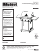
ITEM #0503231 3-Burner stainless steel grill MODEL #RT2417S Master Forge & M Design® is a registered trademark of LF, LLC. All rights reserved. Español p. 39 WARNING Improper installation, adjustment, alteration, service or maintenance can cause injury or property damage. Read this instruction manual thoroughly before installing or servicing this equipment. WARNING 1. Do not store or use gasoline or other flammable vapors and liquids in the vicinity of this or any other appliance. 2.
Table of contents Safety Information ������������������������������������������������������������������������������������������������������������������������������ 3 Safety Tips . . . . . . . . . . . . . . . . . . . . . . . . . . . . . . . . . . . . . . . . . . . . . .
Safety information Please read and understand this entire manual before attempting to assemble, operate or install the product. If you have any questions regarding the product, please call customer service at 1-800-963-0211, 8:00 am to 6:00 pm, EST, Monday- Thursday, 8:00 a.m. to 5:00 p.m., EST, Friday. 3 Lowes.com/masterforge 18 in 12.2 in 1. The installation of this appliance must conform with local codes or, in the absence of local codes, with either the National Fuel Gas Code, ANSI Z223.
Safety information 15. The pressure regulator for LP-gas grill is set for 11-in. water column (WC). Natural gas grill provides a hose assembly which includes a quick-disconnect device, but no pressure regulator. The LP pressure regulator or the natural gas hose assembly must be used. Replacement pressure regulators and hose assemblies must be those specified in the parts list. 16. The cylinder used must include a collar to protect the cylinder valve. 17.
Safety Tips ●● Never pull your grill. Always push it. ●● Never move your grill while it is in operation or still hot. ●● Always use a protected hand when cleaning the grid surface after the post-heating period an when closing the propane tank valve. ●● Use a covered hand during the grilling period.
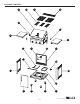
Package Contents A B C D H E G F I J K L U M T N O S R Q 6 P Lowes.
Package Contents PART A B C D E F G H I J K DESCRIPTION Burner Box Heat Tent Main Grid Warming Rack Right Side Shelf Bracket Right Side Shelf Left Side Shelf Left Side Shelf Bracket Drip Tray Support Safety Tank Ring Tank Ring Bracket QUANTITY 1 3 2 1 PART L M N O DESCRIPTION Rear Panel Igniter Right Panel Drip Tray QUANTITY 1 1 1 1 2 P Bottom Panel 1 1 1 Q R Locking Caster Caster 2 2 2 S Door 1 1 1 1 T U Left Panel Front Beam 1 1 7 Lowes.
Hardware Contents AA 3/16-24 x 1/2 in. Screw qty. 49 BB CC 1/4-20 x 5/8 in. Screw qty. 2 AA Battery qty. 1 PREPARATION Before beginning assembly of product, make sure all parts are present. Compare parts with package contents list and hardware contents list. If any part is missing or damaged, do not attempt to assemble the product. Estimated Assembly Time: 30 minutes by 2 people Tools Required for Assembly: Phillips screwdriver (sold separately) 8 Lowes.
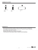
ASSEMBLY INSTRUCTIONS WARNING: The grill should be assembled and placed on a flat, level suface. Compare the parts and hardware with the list and diagrams. Do not attempt assembly if any part is missing or damaged. 1. Attach the locking casters (Q) and the casters (R) to the bottom panel (P) using 12 screws (AA). When this process is completed, turn the bottom panel over. The two locking casters (Q) should be at the back of the grill. 1 AA Q Hardware Used AA 3/16-24 x 1/2 in. Screw x 12 R P 2.
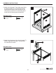
ASSEMBLY INSTRUCTIONS 3. Attach the left panel (T) and right panel (N) to the bottom panel (P). For both the left and right panels, there are three screws for the rear panel (L) and four for the bottom panel. Insert the four bottom panel screws first. 3 AA Hardware Used AA 3/16-24 x 1/2 in. Screw L T x 14 N P 4. Attach the front beam (U) to the left panel (T) and the right panel (N) with 2 screws (AA) on each side as shown. 4 AA Hardware Used AA 3/16-24 x 1/2 in. Screw x4 U 10 Lowes.
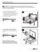
ASSEMBLY INSTRUCTIONS 5. Slide the tank ring bracket (K) onto the end of the safety tank ring (J) as shown. Attach the tank ring bracket to the rear panel (L) with 2 screws (BB) as shown. 5 K BB Hardware Used BB 1/4 - 20x 5/8 in. Screw J x2 6. Attach the drip tray support (I) to the front beam (U) and rear panel (L) with 4 screws (AA) as shown. 6 U I AA Hardware Used AA 3/16-24 x 1/2 in. Screw x4 7. Remove the cap and the nut from the igniter (M).
ASSEMBLY INSTRUCTIONS 8. For the door (S), insert bottom hinge pin into hole on bottom panel (P). Push top hinge pin in the corner of the door to insert into hole in top corner of the right panel (N). Then, put the drip tray (O) onto the drip tray support (I). 8 I O N S 9 A 9. Take the pressure regulator out from under the burner box (A).
ASSEMBLY INSTRUCTIONS 10. Attach the left side shelf bracket (H) to the left of the burner box (A) and the right side shelf bracket (E) to the right of the burner box with 2 screws (AA) on each bracket. 10 H E Hardware Used AA 3/16-24 x 1/2 in. Screw x8 E H Complete Steps 11 - 13 to complete assembly of the left side shelf (G) and right side shelf (F). AA 11 11. Move the side shelves from front to back, making sure the screw on the side shelf brackets fit inside the holes on the side shelves.
ASSEMBLY INSTRUCTIONS 12. Hang the side shelves on the brackets and slowly rotate the side shelves. 12 G 13. Adjust the side shelves until they are aligned with the control box. F 13 F G Control box 14. Plug the main burner igniter wires into the sockets in the igniter. 14 Igniter wires 14 Lowes.
ASSEMBLY INSTRUCTIONS 15. Place the heat tents (B), main grids (C) and warming rack (D) into the burner box (A). Remove the battery cap on the igniter (M) and insert a AA battery (CC) with the positive end facing outward. Replace the cap. 15 D C B Insert AA battery 15 Lowes.
ASSEMBLY INSTRUCTIONS IMPORTANT CHECK SPARKS After you complete your grill assembly, test your ignition system with the GAS OFF. Check for continuous sparks when pushing in the knob ignition system. For the side burner, sparks can be seen directly. For main burners, the ignition system is positioned next to each burner inside the burner box.
NATURAL GAS CONVERSION INSTRUCTIONS Should you decide to convert your gas grill from liquid propane gas to natural gas, use NG Conversion Kit Item #0050772. The #0050772 kit contains orifices for various grill models. Please select the orifices as listed and discard the rest. Follow the conversion instruction provided with the kit. Main Burner Conversion 16. Pull off the R-pins and take the main burners out. Adjust main burners’ air shutters by loosening the air shutter screws.
NATURAL GAS CONVERSION INSTRUCTIONS 18. Remove the LP orifices first with the orifice removal tool, then install the NG orifice. Make sure you are using the correct orifice, marked “1.37”. When this step completed, install the main burners back to the firebox and secure to the bracket with the R-pins. Make sure the orifices are aligned with the burners and the ignition pins are installed in their original positions. Check the sparks before operating the grill. Change to 10 ft. NG hose 19.
COOKING WITH GAS For Portable LP-Gas Connection The cabinet has an opening in the bottom panel that allows a 20 lb. gas tank bottom flange to drop into place (tank sold separately). This will help to lock the tank in place. Before installing your gas tank, lift up the safety tank ring (as shown in Fig. 21a). After positioning the tank in the opening, lower the safety tank ring to lock the tank in place. Use only a 20 lb. gas tank (see LP Gas Safety Requirements for Additional Information). As shown in Fig.
COOKING WITH GAS a. Hand Assembly: 1. Make certain the tank valve and all the appliance valves are in the “OFF” position. 2. When connecting the regulator/burner valve assembly to the tank valve, turn the large plastic nut clockwise until it stops. 3. Gas will not flow unless the plastic nut is completely connected. 4. HAND TIGHTEN ONLY. b. Hand Disassembly: 1. Make certain the tank valve and all the appliance valves are in the “OFF” position. 2.
COOKING WITH GAS For Natural Gas Connection Preparing: 1. Turn off gas supply and then remove cap on gas supply side. 2. Recommended: Install a shut-off valve on gas supply side before installing the socket. 3. Socket should be installed by an authorized technician in accordance with the national fuel gas code (NFPA 54/ANSI223.1). 4. Before inserting plug, turn on gas supply and leak test all connections including the stem of the shut-off valve and the opening of the socket.
COOKING WITH GAS LP Gas If your grill is for LP gas, the regulator supplied is set for an 11-in. water column (WC) and is for use with LP gas only. The factory-supplied regulator and hose must be used with a 20-lb. LP gas tank. Natural Gas Your grill is natural gas convertible. NG kit sold separately (Item #0050772). Please follow the manual to convert your grill to natural gas. If your grill is for natural gas, it is set for a 7-in. water column (WC) and is for use with natural gas only.
COOKING WITH GAS (c) Provided with a tank connection device compatible with the connection for outdoor cooking appliances. The tank should be 12 in. in diameter and 18-1/2 in. tall and be equipped with a Type-1 fitting. The tank supply system must be arranged for vapor withdrawal. The tank used must include a collar to protect the cylinder valve. Do not operate the gas grill indoors or in any enclosed area. If the gas grill is not in use, the gas must be turned off at the supply tank.
COOKING WITH GAS When transporting the tank to your local propane gas dealer, make sure the valve is closed tightly and the protective cover is in place. Position the tank securely in an upright position so it will not roll around your vehicle. If you plan to make stops for shopping or errands, have your liquid propane tank filled at the last stop before going home. Again, make certain the refilled tank is secure and in an upright position. When you return home, remove the refilled tank from your vehicle.
COOKING WITH GAS The proper way to fill a tank is by weight. The empty tank should be placed on a scale. The scale weights should be readjusted to a weight that would allow up to 80% of the total weight. The filling operation must end once the tank is filled to 80% of its total capacity. If the tank is not completely empty, the scale readjustment must be changed to consider the propane (LP) already in the tank.
COOKING WITH GAS Grill Lighting Instructions Checking orifices’ alignment with burners Orifices may shift during assembly and movement; therefore, check the orifices’ alignment with the burners according to the following illustrations before lighting. Orifice stud inside the air shutter Fig. 26 Main Burner and Orifice Relationship Lighting Instructions GRILL OFF 1. Read instructions before lighting your grill. 2. Open lid during lighting. 3. Fully open cylinder valve. 4.
OPPERATING INSTRUCTIONS WARNING: 1. Make sure the hood is completely open each time you attempt to light the grill. Failure to open the hood could lead to delayed ignition resulting in bodily harm. 2. This grill is equipped with a flame-observation hole in the side panel. Wear protective mitts before using the flame watch. CAUTION: It is important to inspect the full length of the gas line hose.
OPPERATING INSTRUCTIONS Fig. 28 Match/Paper Lighting Illustration Breaking in Your Grill When firing your grill for the first time, it is advisable to run the main burner(s) on “HIGH” for 20 minutes with the hood down and then turn the main burners off. This tempers the grill. Preheating Grill It is extremely important that your grill be up to temperature before you begin using it. After lighting, close the hood and preheat the grill on “HIGH” for 15 minutes.
OPPERATING INSTRUCTIONS We recommend always cooking with the lid CLOSED if you are in a windy area or colder climate. Your grill has been designed and constructed to give you maximum flexibility and cooking performance. Be creative. Try different cooking methods on your grill to determine which suits your needs best. There is no right or wrong way to cook, just different cooking styles. Get creative and enjoy! WARNING: Please remember this is an outdoor gas grill.
Care and maintenance Checking the Flame Refer to Fig. 29 below (side view of grill). Check the flame after the grill is lit. Make sure you have a stable, mostly blue flame. Flame Observation Hole Fig. 29 Air Shutter Adjustment The main burner shutters are adjusted at the factory for your convenience. The settings are: (1) Full open for LP gas. (2) Half open for NG gas. If you desire to fine tune your shutter adjustment (or if your flame is more yellow rather than blue), please follow this procedure.
Care and maintenance CAUTION: If the natural gas conversion kit is used, remember to adjust the air shutter of main burner (for details, please read the NG conversion kit manual). Replacing the Battery 1. Unscrew the cap on the battery compartment and remove the old battery. 2. Replace with a new battery and re-install the cap. Note: The negative (-) side of the battery goes in first. Please refer to the mark on the side of the cap. Battery Fig.
Care and maintenance the port) to clean clogged ports. Do not enlarge any ports. Make sure the burners are dry before installing them back to the grill. See Fig. 33. Fig. 33 Air Shutter Spiders and insects can nest inside the burners of this or any other grill and cause the gas to flow from the front of the burner. This could cause a fire to occur behind the valve panel, thereby damaging the grill and making it unsafe to operate.
Care and maintenance After use, close hood and turn burners to HIGH for 15 min. for self-cleaning, grease burn off.
Troubleshooting Problem Possible Cause Corrective Action Grill or side cooker 1. The ignition wire came off will not light. the electrical igniter. 2. The distance between the ignition pin and the burner is greater than 0.1-0.2 inch (side burner). 3. The ignition wire is broken. 4. The battery has died. 5. The battery is in the wrong polarity. 6. The electrode tip does not produce sparks at the burner port. 7. No gas supplied. 8. Air shutter opening is too big.
Troubleshooting Problem Low heat, natural gas. Possible Cause Corrective Action Gas pressure is significantly affected by gas line and length of gas line from house gas line. Check your gas line and make corrections by followong the chart below. From House to Grill Distance Tubing Size Up to 25 ft. 3/8 in. diameter 26 - 50 ft. 1/2 in. diameter 1/3 in. of run 1/2 in. 51 - 100 ft. 2/3 in. of run 3/4 in. Low heat, LP gas.
WARRANTY Proof of purchase is required to access this warranty program, which is in effect from the date of purchase. Customers will be subject to parts, shipping, and handling fees if unable to provide proof of purchase or after the warranty has expired. Before returning to your retailer, call our customer service department at 1-800-963-0211, 8:00 a.m. to 6:00 p.m., EST, Monday-Thursday, 8:00 a.m. to 5:00 p.m., EST, Friday. Limited Warranty 5-Year Warranty on stainless steel burners.
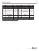
REPLACEMENT PARTS LIST 1 11 8 S1 9 10 7 6 5 4 3 2 S2 12 S3 13 15 14 S7 25 24 S4 20 23 26 17 18 19 16 29 S1 27 28 38 21 22 31 30 39 40 S5 S5 S6 37 36 35 34 33 32 For replacement parts, call our customer service department at 1-800-963-0211, 8:00 a.m. to 6:00 p.m., EST, Monday- Thursday, 8:00 a.m. to 5:00 p.m., EST, Friday. 37 Lowes.
REPLACEMENT PARTS LIST Part Description Part # Part Description Part # 1 HEAT TENT 2518SL-2003-N 25 MANIFOLD RT2417S-00-3200 2 COOKING GRID RT2417S-00-2010 26 LEFT PANEL RT2417S-00-1700 3 WARMING RACK RT2417S-00-2020 27 SAFETY TANK RING RT2417S-00-1203 4 TEMPERATURE GAUGE 2518-3-8012 28 TANK RING BRACKET 2518SL-1203 5 TEMPERATURE GAUGE BEZEL 3218LTN-00-4001 29 REAR PANEL RT2417S-00-1200 6 TEMPERATURE GAUGE SLEEVE 3218LT-00-4009 30 IGNITER RT2417S-00-8004 7 HOOD RT24
ARTÍCULO #0503231 PARRILLA DE ACERO INOXIDABLE DE 3 QUEMADORES MODELO #RT2417S ® Master registered Master Forge Forge & &M M Design Design®isesa una marca registrada trademark LF, LLC. rights reserved. de LF, LLC.ofTodos los All derechos reservados. ADVERTENCIA La instalación, el ajuste, la alteración, el servicio o el mantenimiento inadecuados pueden causar lesiones o daños materiales. Lea este manual de instrucciones detenidamente antes de instalar o dar servicio a este equipo. ADVERTENCIA 1.
CONTENIDO Información de seguridad ���������������������������������������������������������������������������������������������������������������� 41 Consejos de seguridad ������������������������������������������������������������������������������������������������������������������� 43 Contenido del paquete ���������������������������������������������������������������������������������������������������������������������� 44 Aditamentos . . . . . . . . . . . . . . . . . . . . .
INFORMACIÓN DE SEGURIDAD Por favor, lea detenidmente este manual completo antes de tratar de ensamblar, usar o instalar el producto. Si tiene preguntas sobre el producto, llame por favor al servicio al cliente al 1-800-9630211, de 8:00 am a 6:00 pm (hora del este) de lunes a jueves o de 8:00 a.m. a 5:00 p.m. (hora del este) los viernes. 41 Lowes.com/masterforge 45,72cm 30,98cm 1.
INFORMACIÓN DE SEGURIDAD 15. El regulador de presión para la parrilla a gas de propano líquido está regulado para una columna de agua de 27,94 cm. La parrilla a gas natural cuenta con una manguera que incluye un dispositivo de desconexión rápida pero no tiene regulador de presión. Se debe usar un regulador de presión de propano líquido o una manguera de gas natural. Los reguladores de presión y las mangueras de repuesto deben ser los especificados en la lista de piezas. 16.
CONSEJOS DE SEGURIDAD ●● Nunca hale su parrilla para moverla, empújela siempre. ●● Nunca mueva su parrilla cuando esté en uso o caliente. ●● Use siempre protección para las manos cuando limpie la superficie de la parrilla después de ●● ●● ●● ●● ●● ●● ●● ●● ●● ●● ●● ●● ●● ●● ●● ●● ●● ●● ●● ●● ●● ●● calentarse y cuando cierre la válvula del tanque de propano. Use protección para las manos durante el uso de la parrilla.
CONTENIDO DEL PAQUETE A B C D H E G F I J K L U M T N O S R Q 44 P Lowes.
CONTENIDO DEL PAQUETE PIEZA A B C D E F G H I J K DESCRIPCIÓN CANTIDAD Cámara de 1 quemadores Placa de calor 3 Parrilla principal 2 Parrilla para calentar 1 Soporte del estante 2 lateral derecho Estante lateral 1 derecho Estante lateral 1 izquierdo Soporte del estante 2 lateral izquierdo Soporte de la bandeja 1 para goteo Aro de seguridad del 1 tanque Soporte del aro del 1 tanque PIEZA DESCRIPCIÓN CANTIDAD L Panel posterior 1 M N O Encendedor Panel derecho Bandeja para goteo 1 1 1 P Panel infer
ADITAMENTOS AA Tornillo de 3/16-24 x 1/2 pulg. Cant. 49 BB CC Tornillo de 1/4-20 x 5/8 pulg. Cant. 2 Batería AA Cant. 1 PREPARACIÓN Antes de comenzar a ensamblar el producto, asegúrese de tener todas las piezas. Compare las piezas con la lista del contenido del paquete y la lista de aditamentos. Si hubiera alguna pieza faltante o dañada, no ensamble el producto.
INSTRUCCIONES DE ENSAMBLAJE ADVERTENCIA: La parrilla debe ser ensamblada y colocada sobre una superficie plana y nivelada. Compare las piezas y los aditamentos con la lista y los diagramas. No trate de ensamblar la parrilla si hubiera alguna pieza faltante o dañada. 1. Acople las ruedas con cierre (Q) y las ruedas (R) al panel inferior (P) usando 12 tornillos (AA). Cuando complete este proceso, dele vuelta al panel inferior.
INSTRUCCIONES DE ENSAMBLAJE 3. Acople el panel izquierdo (T) y el panel derecho (N) al panel inferior (P). Ambos paneles, el izquierdo y el derecho, llevan tres tornillos para el panel posterior (L) y cuatro para el panel inferior. Introduzca los cuatro tornillos del panel inferior primero. 3 AA Aditamento AA Tornillos de 3/16-24 x 1/2 pulg. L T x 14 N P 4. Acople la barra frontal (U) al panel izquierdo (T) y al panel derecho (N) con 2 tornillos (AA) a cada lado como se muestra.
INSTRUCCIONES DE ENSAMBLAJE 5. Deslice el soporte del aro del tanque (K) hacia el final del aro de seguridad del tanque (J), como se muestra. Fije el soporte del aro del tanque al panel posterior (L) con 2 tornillos (BB), como se muestra. 5 K BB Aditamento BB Tornillos de 1/4-20 x 5/8 pulg. J x2 6. Acople el soporte de la bandeja de goteo (I) a la barra frontal (U) y al panel posterior (L) con 4 tornillos (AA) como se muestra. 6 U I AA Aditamento AA Tornillos de 3/16-24 X 1/2 pulg. x4 7.
Instrucciones de ensamblaje 8. Para montar la puerta (S), introduzca el pasador de la bisagra inferior en el orificio del panel inferior (P). Empuje el pasador de la bisagra superior en la esquina de la puerta para introducirlo en el orificio que está en la esquina superior del panel derecho (N). Después, coloque la bandeja de goteo (O) sobre el soporte para la bandeja (I). 8 I O N S 9. Tome el regulador de presión de debajo de la cámara de los quemadores (A).
Instrucciones de ensamblaje 10. Acople el soporte del estante lateral izquierdo (H) a la parte izquierda de la cámara de los quemadores (A) y el soporte del estante lateral derecho (E) a la parte derecha de la cámara de los quemadores con 2 tornillos (AA) en cada soporte. 10 H E Aditamento AA Tornillos de 3/16-24 x 1/2 pulg. x8 E H Complete los pasos 11 al 13 para terminar de ensamblar el estante lateral izquierdo (G) y el estante lateral derecho (F). AA 11 11.
Instrucciones de ensamblaje 12. Cuelgue los estantes laterales en los soportes y rote lentamente los estantes laterales. 12 G F 13 13. Ajuste los estantes laterales hasta que queden alineados con la caja de control. F G Caja de control 14. Enchufe los alambres de encendido del quemador principal en las tomas del encendedor. 14 Alambres del encendedor 52 Lowes.
Instrucciones de ensamblaje 15. Coloque las placas de calor (B), las parrillas principales (C) y la parrilla para calentar (D) en la cámara de los quemadores (A). Retire la tapa del encendedor (M) e inserte una batería AA (CC) con el polo positivo hacia afuera. Coloque la tapa de nuevo. 15 D C B Inserte una batería AA 53 Lowes.
Instrucciones de ensamblaje IMPORTANTE REVISE LAS CHISPAS Después de terminar de ensamblar la parrilla, pruebe el sistema de encendido con el GAS APAGADO. Fíjese si hay chispas continuas cuando presione el botón de encendido. Para el quemador lateral, las chispas se pueden ver directamente. Para los quemadores principales, el sistema de encendido está colocado al lado de cada quemador en la cámara de los quemadores.
INSTRUCCIONES DE CONVERSIÓN DE GAS NATURAL Si decide convertir su parrilla a gas de propano líquido a gas natural, use el kit de conversión a GN Artículo # 0050772. El kit #0050772 contiene orificios para diferentes modelos de parrilla. Por favor, elija los orificios que se enumeran a continuación e ignore el resto. Siga las instrucciones para la conversión que se incluyen en el kit. Conversión del quemador principal 16.
INSTRUCCIONES DE CONVERSIÓN DE GAS NATURAL 18. Quite los orificios de LP primero con la herramienta de eliminación de orificios, a continuación, instalar el orificio NG. Asegúrese de que está utilizando el orificio correcto, marcó 1.37. Cuando este paso, instale los quemadores principales de nuevo a la cámara de combustión y asegurar al soporte con las R-PIN. Asegúrese de que los orificios están alineados con los quemadores y los pasadores de ignición están instalados en sus posiciones originales.
Cocción con gas Para la conexión del gas propano en parrillas portátiles El gabinete tiene una abertura en el panel inferior que permite que el reborde del fondo de un tanque de gas de 20 lb. caiga en su sitio (el tanque se vende por separado). Esto ayuda a asegurar el tanque en su lugar. Antes de instalar el tanque de gas, levante el aro de seguridad del tanque (como se muestra en la Fig. 21a). Después de colocar el tanque en la abertura, baje el aro de seguridad del tanque para trabarlo en su sitio.
Cocción con gas a. Montaje manual: 1. Cerciórese de que la válvula del tanque y todas las demás válvulas del equipo estén en la posición OFF (apagado). 2. Al conectar la válvula del regulador/quemador a la válvula del tanque, gire la tuerca grande plástica en la dirección del reloj hasta que se detenga. 3. El gas no va a salir a menos que la tuerca plástica esté totalmente conectada. 4. APRIÉTELA SOLO CON LA MANO. b. Desmontaje manual. 1.
Cocción con gas Para la conexión de gas natural Preparación: 1. Cierre la llave del gas y después quite la tapa del lado de salida del gas. 2. Se recomienda: Instalar una válvula de cierre en el lado de salida del gas antes de instalar el enchufe. 3. El enchufe debe ser instalado por un técnico autorizado de acuerdo al código nacional de regulación del gas combustible (NFPA 54/ANSI223.1). 4.
Cocción con gas Gas propano líquido Si su parrila es de gas propano líquido, el regulador suministrado está ajustado para una columna de agua (WC) de 27,94 cm y es para uso con gas propano líquido solamente. El regulador y la manguera instalados de fábrica se deben usar con un tanque de propano líquido de 20 libras. Gas Natural Su parrilla se puede convertir para gas natural. El kit de conversión a gas natural se vende por separado (artículo #0050772).
Cocción con gas (c) Contar con un dispositivo de conexión del tanque compatible con la conexión para aparatos para cocinar en exteriores. El tanque debe medir 30,48 cm de diámetro y 46,99 cm de alto, y debe estar equipado con un acoplador del tipo 1. El sistema de suministro del tanque debe ser capaz de eliminar el vapor. El tanque empleado debe tener un collarín para proteger la válvula del cilindro. No use la parrilla a gas en interiores ni en áreas cerradas.
Cocción con gas Cuando transporte su tanque al distribuidor de gas, asegúrese de que la válvula esté bien cerrada y que la cubierta protectora esté en su lugar. Coloque el tanque en un lugar seguro en posición vertical para que no ruede en su vehículo. Si va a parar varias veces para hacer compras o gestiones, trate de que llevar el tanque a rellenar sea la última tarea antes de regresar a casa. Nuevamente, asegúrese de que el tanque lleno esté firme y en posición vertical.
Cocción con gas La manera apropiada de rellenar el tanque es a partir del peso. El tanque vacío se debe colocar en una balanza y los contrapesos de la balanza se deben reajustar a un peso que solo permita el 80% del peso total. La operación de llenado debe cesar en cuanto el tanque se llene hasta el 80% de su capacidad total. Si el tanque no está totalmente vacío, el reajuste de la balanza debe cambiarse para considerar el propano que hay en el interior del tanque.
Cocción con gas Instrucciones para encender la parrilla Revisión de la alineación de los orificios con los quemadores Los orificios pueden haberse movido durante el ensamblaje y el traslado; por lo tanto, revise que los orificios estén alineados con los quemadores siguiendo las ilustraciones siguientes antes de encender la parrilla. Vástago con orificio en el obturador de aire Fig. 26 Relación entre el quemador principal y el orificio Instrucciones de encendido GRILL OFF 1.
Instrucciones de uso ADVERTENCIA: 1. Asegúrese de abrir completamente la tapa cada vez que vaya a encender la parrilla. Si no abre la tapa, pudiera producirse un encendido retardado, lo que pudiera ocasionar lesiones. 2. Esta parrilla cuenta con un orificio en el panel lateral para observar la llama. Use guantes de protección antes de usar este visor de llama. PRECAUCIÓN: Es importante inspeccionar toda la manguera de gas.
Instrucciones de uso Fig. 28 Ilustración del encendido con cerilla/papel Primer uso de su parrilla Cuando encienda su parrilla por primera vez, se recomienda usar los quemadores principales a fuego alto (HIGH) durante 20 minutos con la tapa cerrada y apagar luego los quemadores principales. Eso tiempla la parrilla. Precalentamiento de la parrilla Es tremendamente importante que su parrilla alcance la temperatura deseada antes de comenzar a usarla.
Instrucciones de uso Le recomendamos cocinar siempre con la tapa CERRADA si usted está un una zona de mucho viento o clima más frío. Su parrilla ha sido diseñada y fabricada para brindarle una máxima flexibilidad y rendimiento de cocción. Despliegue su creatividad, pruebe diferentes métodos de cocción en su parrilla para determinar lo que más le gusta. En realidad, no hay maneras correctas o incorrectas, solo estilos diferentes.
Cuidado y mantenimiento Revisión de la llama Refiérase a la Fig. 29 que aparece abajo (vista lateral de la parrilla). Revise la llama después de encender la parrilla. Asegúrese de tener una llama estable y mayormente azul. Orificio para observar la llama Fig. 29 Ajuste del obturador de aire Para su mayor conveniencia, los obturadores de aire de los quemadores principales están ajustados de fábrica. Los ajustes son los siguientes: (1) Abierto totalmente para gas propano. (2) Medio abierto para gas natural.
Cuidado y mantenimiento PRECAUCIÓN: Si usa el kit de conversión a gas natural, recuerde ajustar el obturador del quemador principal (para más detalles, vea el manual del kit de conversión a GN). Reemplazo de la batería 1. Desenrosque la tapa del compartimento de la batería y retire la batería vieja. 2. Reemplácela con una batería nueva y coloque nuevamente la tapa. Nota: El polo negativo (-) de la batería se inserta primero. Refiérase por favor a la marca en el lado de la tapa. Batería Fig.
Cuidado y mantenimiento Use un alfiler (más pequeño que el orificio) para limpiar los orificios obstruidos. No agrande ningún orificio. Asegúrese de que los quemadores estén secos antes de instalarlos nuevamente en la parrilla. Vea la Fig. 33. Obturador de aire Fig. 33 Las arañas y los insectos pueden anidar adentro de los quemadores de esta o cualquier parrilla y ocasionar que el gas fluya de la parte frontal del quemador.
Cuidado y mantenimiento Después de cada uso, cierre la tapa y deje los quemadores funcionando por 15 minutos a fuego alto (HIGH) para la autolimpieza y quemar residuos de grasa.
deteccíon de problemas Problema La parrilla o el quemador lateral no enciende. Causa Posible Solución 1. El cable de encendido se 1. Vuelva a conectar el cable de encendido al encendedor desprendió del encendedor eléctrico eléctrico. 2. La distancia entre el pasador de encendido y el quemador es más de 2,54 - 5,08mm pulg.(quemador lateral). 3. El cable de encendido está roto. 4. La batería murió. 5. La batería está con la polaridad incorrecta. 6.
Detección de problemas Problema Poco calor, gas natural. Causa Posible Solución La presión del gas se ve afectada significativamente por la línea de gas y la longitud de la línea de gas desde la línea de gas de la casa. Revise su línea de gas y haga las correcciones necesarias siguiendo la tabla de abajo.
GARANTÍA Se requiere una prueba de la compra para acceder a este programa de garantía que entra en vigor a partir de la fecha de compra. Los clientes serán responsables de pagar los costos de las piezas, el envío y el manejo si no se presenta una prueba de compra, o después del vencimiento de la garantía. Antes de regresar a la tienda, llame a nuestro departamento de servicio al cliente al 1-800-963-0211, de 8 a.m. a 6 p.m., hora del este, de lunes a jueves, y de 8 a.m. a 5 p.m., hora del este, los viernes.
Lista de piezas de repuesto 1 11 8 S1 9 10 7 6 5 4 3 2 S2 12 S3 13 15 14 S7 25 24 S4 20 17 16 29 S1 27 28 38 21 22 18 19 26 23 31 30 39 40 S5 S5 S6 37 36 34 35 33 32 Para encargar piezas de repuesto, llame al departamento de servicio al cliente al 1-800-963-0211, de 8:00 a.m. a 6:00 p.m., hora estándar del este, de lunes a jueves, y de 8:00 a.m. a 5:00 p.m., hora estándar del este, los viernes. 75 Lowes.
Lista de piezas de repuesto Pieza Descripción # de pieza Pieza Descripción # de pieza 25 1 PLACA DE CALOR 2518SL-2003-N COLECTOR RT2417S-00-3200 2 PARRILLA PARA COCCIÓN RT2417S-00-2010 26 PANEL IZQUIERDO RT2417S-00-1700 3 PARRILLA PARA CALENTAR RT2417S-00-2020 27 ARO DE SEGURIDAD DEL TANQUE RT2417S-00-1203 4 INDICADOR DE TEMPERATURA 2518-3-8012 28 SOPORTE DEL ARO DEL TANQUE 2518SL-1203 5 MOLDURA DEL INDICADOR DE TEMPERATURA 3218LTN-00-4001 29 PANEL TRASERO RT2417S-00-1200 6