
User's Manual

Master Lock Company LLC, Milwaukee, WI 53154 U.S.A. | 800-574-7260
©2017 Master Lock Company LLC | All Rights Reserved.
9 P57672 REV A
4.
Install
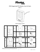
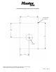
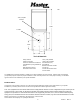
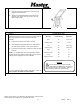
1. Pass the Keypad wires through the center hole in the
prepared mounting surface.
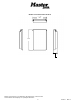
2. Attach the assembled Bluetooth Keypad 27213 and
Weather Cover 27211 using (4) #10-24 x 1/2” Long
Button Head Screws.
Activating the Keypad
5.
Connect
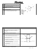
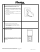
Follow the keypad wiring chart to connect the Keypad cable to
the keypad terminal connector provided with the Door
Controller.
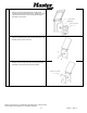
1. Loosen the terminal screws on the connector
2. Insert stripped and prepared wire ends. Make sure the
wire pairs remain together in their correct sequence.
3. Tighten the terminal screws, ensuring the wires are firmly
engaged
NOTE: The Keypad cable can be extended using 22AWG
twisted pair wire to a maximum total length of 50 feet using a
splicing method appropriate for your installation.
For more information about making connections, review the
Door Controller Installation and User Manual
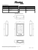
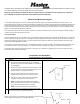
Keypad Wiring Chart
Wire Color
Terminal Position
Signal Name
Black
BK
Ground GND
White/Black White
WE
V+ 3VDC
Red
RD
Battery Jump
White/Red White
WE
Tamper input
Brown
BN
TX +
White/Brown White
WE
TX-
Orange
OE
RX+
White/Orange White
WE
RX-
Configuration
Warning!
Ensure Power Source and Door Controller
Battery Board Switch are OFF before connecting or
disconnecting devices to the Controller. Failure to
observe this precaution may cause damage.