R PORTABLE FORCED AIR HEATERS OWNER’S MANUAL Heater Sizes: 35,000 70,000 100,000 150,000 Btu/Hr Models: B35CEA, B70CEA, B100CEA, and B150CEA IMPORTANT: Read and understand this manual before assembling, starting or servicing heater. Improper use of heater can cause serious injury. Keep this manual for future reference.
R PORTABLE FORCED AIR HEATERS SAFETY INFORMATION WARNINGS • • IMPORTANT: Read this Owner’s Manual carefully and completely before trying to assemble, operate, or service this heater. Improper use of this heater can cause serious injury or death from burns, fire, explosion, electrical shock, and carbon monoxide poisoning. DANGER: Carbon monoxide poisoning may lead to death! Carbon Monoxide Poisoning: Early signs of carbon monoxide poisoning resemble the flu, with headaches, dizziness, and/or nausea.
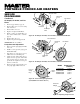
OWNER’S MANUAL PRODUCT IDENTIFICATION Hot Air Outlet UNPACKING 1. 2. 3. Handle Upper Shell Fan Guard Lower Shell Air Filter End Cover Fuel Tank Fuel Cap Side Cover Flame-Out Control Reset Button Power Cord Figure 1 - 35/70,000 Btu/Hr Models Hot Air Outlet Upper Shell Lower Shell Fuel Cap Fan Guard Fuel Tank Side Cover Flame-Out Control Reset Button Figure 2 - 100/150,000 Btu/Hr Models 104468 3 Power Cord Remove all packing items applied to heater for shipment. Remove all items from carton.
R PORTABLE FORCED AIR HEATERS ASSEMBLY 2. (FOR 100,000 AND 150,000 BTU/HR MODELS ONLY) 3. These models are furnished with wheels and handles. Wheels, handles, and the mounting hardware are found in the shipping carton. 4. Tools Needed • Medium Phillips Screwdriver • 3/8" Open or Adjustable Wrench • Hammer 1. 5. Place cap nuts on axle ends. Gently tap with hammer to secure. Place heater on wheel support frame. Make sure air inlet end (rear) of heater is over wheels.
OWNER’S MANUAL THEORY OF OPERATION OPERATION WARNING: Review and understand the warnings in the Safety Information Section. They are needed to safely operate this heater. Follow all local codes when using this heater. The Fuel System: The air pump forces air through the air line. The air is then pushed through the burner head nozzle. This air causes fuel to lift from the tank. A fine mist of fuel is sprayed into the combustion chamber. The Air System: The motor turns the fan.
R PORTABLE FORCED AIR HEATERS STORING, TRANSPORTING, OR SHIPPING Note: If shipping, transport companies require fuel tanks to be empty. 1. Drain fuel tank. Note: Some models have drain plug on underside of fuel tank. If so, remove drain plug to drain all fuel. If heater does not have drain plug, drain fuel through fuel cap opening. Be sure all fuel is removed. 2. Replace drain plug if provided. 3. If any debris is noted in old fuel, add 1 or 2 quarts of clean kerosene to tank, stir, and drain again.
OWNER’S MANUAL TROUBLESHOOTING WARNING: Never service heater while it is plugged in, operating, or hot. Severe burns and electrical shock can occur. OBSERVED FAULT POSSIBLE CAUSE REMEDY Heater ignites, but flame-out control shuts off heater after a short period of time. 1. Wrong pump pressure 1. See Pump Pressure Adjustment, page 10. 2. See Air Output, Air Intake and Lint Filters, page 10. 3. See Fuel Filter, page 8. 4. See Nozzle, page 11. 5. Clean photocell lens. 6. Replace flame-out control. 2.
R PORTABLE FORCED AIR HEATERS SERVICE PROCEDURES Upper Shell Upper Shell Fan Guard WARNING: Never service heater while it is plugged in, operating, or hot. Severe burns and electrical shock can occur. Fan Guard Upper Shell Removal 1. 2. 3. Remove screws and lock washers along each side of heater using 5/16" nutdriver. These screws attach upper and lower shells together. Lift upper shell off. Remove fan guard. Fuel Filter (35/70,000 Btu/Hr Models) 1. Remove side cover screws using 5/16" nut-driver.
OWNER’S MANUAL SERVICE PROCEDURES Continued Spark Plug (35,000 Btu/Hr Model) 1. Remove upper shell (see page 8). 2. Remove fan (see page 13). 3. Remove fuel and air line hoses from nozzle assembly. 4. Remove spark plug wire from spark plug. 5. Remove two screws using 5/16" nutdriver and remove burner strap. 6. Place hex-body of spark plug into vise and tighten. 7. Remove spark plug mounting nut using 11/16" open-end wrench. 8. Remove burner strap from spark plug. 9.
R PORTABLE FORCED AIR HEATERS Air Intake Filter SERVICE PROCEDURES Filter End Cover Continued Fan Guard Air Output, Air Intake, and Lint Filters 1. 2. 3. 4. 5. 6. 7. Remove upper shell (see page 8). Remove filter end cover screws using 5/16" nut-driver. Remove filter end cover. Replace air output and lint filters. Wash or replace air intake filter (see Preventative Maintenance Schedule, page 6). Replace filter end cover. Replace fan guard and upper shell.
OWNER’S MANUAL SERVICE PROCEDURES Burner Strap Continued Nozzle (35,000 Btu/Hr Model) 1. Remove upper shell (see page 8). 2. Remove fan (see page 13). 3. Remove fuel and air line hoses from nozzle assembly. 4. Turn nozzle assembly 1/4 turn to left and pull toward motor to remove. 5. Place plastic hex-body into vise and lightly tighten. 6. Carefully remove nozzle from the nozzle adapter using 5/8" socket wrench. 7. Blow compressed air thru face of nozzle. This will free any dirt in nozzle area. 8.
R PORTABLE FORCED AIR HEATERS Blade SERVICE PROCEDURES Air Intake Filter Pump Plate Continued Filter End Cover Pump Rotor (Procedure if rotor is binding) 1. Remove upper shell (see page 8). 2. Remove filter end cover screws using 5/16" nut-driver. 3. Remove filter end cover and air filters. 4. Remove pump plate screws using 5/16" nut-driver. 5. Remove pump plate. 6. Remove rotor, insert, and blades. 7. Check for debris in pump. If debris is found, blow out with compressed air. 8.
OWNER’S MANUAL SERVICE PROCEDURES SPECIFICATIONS Continued Fan IMPORTANT: Remove fan from motor shaft before removing motor from heater. The weight of the motor resting on the fan could damage the fan pitch. 1. Remove upper shell (see page 8). 2. Use 1/8" allen wrench to loosen setscrew which holds fan to motor shaft. 3. Slip fan off motor shaft. 4. Clean fan using a soft cloth moistened with kerosene or solvent. 5. Dry fan thoroughly. 6. Replace fan on motor shaft.
R PORTABLE FORCED AIR HEATERS 3 ILLUSTRATED PARTS BREAKDOWN 1 2 4 35,000 BTU/HR 11-5 11-1 5 11-2 6 11 8 7 9 11-4 15 11-3 13 22 13 18 16 23 17 19 20 24 22 21 21 33 34 39 27 31 41 43 29 26 42 30 37 25 28 12 35 32 36 18-1 18-2 18-18 18-4 18-5 18-6 18-3 22 18-7 18-8 18-17 18-16 40 18-9 18-15 18-10 18-11 18-14 Motor and Pump Assembly 14 10 38 18-12 18-13 14 104468
OWNER’S MANUAL This list contains replaceable parts used in your heater. When ordering parts, be sure to provide the correct model and serial numbers (from the model plate), then the part number and description of the desired part. PARTS LIST 35,000 BTU/HR KEY NO.
R PORTABLE FORCED AIR HEATERS 3 ILLUSTRATED PARTS BREAKDOWN 1 2 4 70,000 BTU/HR 5 10 7 6 14 8 12 12 11 18 15 25 19 23 17 24 16 Burner Head Assembly 20 21 10-1 26 21 10-2 10-4 11 35 10-5 36 41 43 29 10-3 45 27 10-7 31 28 44 32 30 39 33 38 22 10-6 18-1 37 18-2 34 18-18 18-4 40 18-5 18-6 18-3 11 18-7 13 9 18-8 18-17 18-16 18-15 18-10 18-11 18-14 Motor and Pump Assembly 42 18-9 18-12 18-13 16 104468
OWNER’S MANUAL PARTS LIST This list contains replaceable parts used in your heater. When ordering parts, be sure to provide the correct model and serial numbers (from the model plate), then the part number and description of the desired part. 70,000 BTU/HR KEY NO.
R PORTABLE FORCED AIR HEATERS 2 ILLUSTRATED PARTS BREAKDOWN 1 100,000 BTU/HR 3 4 5 8 12 13 14 8-1 7 8-2 8-4 9 15 8-5 10 8-3 11 17 30 31 20 8-7 25 26 21 28 27 23 8-6 9 24 Burner Head Assembly 33 34 36 44 22 18 19 35 32 37 38 13-1 13-2 13-3 29 39 16 13-4 13-5 13-6 43 42 9 41 13-7 13-18 40 13-8 6 13-17 13-16 13-9 13-10 13-15 13-14 13-11 13-13 Motor and Pump Assembly 13-12 18 104468
OWNER’S MANUAL This list contains replaceable parts used in your heater. When ordering parts, be sure to provide the correct model and serial numbers (from the model plate), then the part number and description of the desired part. PARTS LIST 100,000 BTU/HR KEY NO.
R PORTABLE FORCED AIR HEATERS 2 ILLUSTRATED PARTS BREAKDOWN 1 3 150,000 BTU/HR 4 5 8 12 13 14 7 8-1 9 15 8-2 8-4 10 8-5 11 17 30 31 8-3 46 25 26 8-7 21 20 28 27 23 9 24 8-6 33 34 36 Burner Head Assembly 22 18 19 44 35 32 37 38 29 13-1 39 16 13-2 13-3 13-4 13-5 45 42 13-6 41 43 40 13-7 13-18 6 13-8 13-17 13-16 13-15 13-9 13-10 13-14 13-11 13-13 Motor and Pump Assembly 13-12 20 104468
OWNER’S MANUAL This list contains replaceable parts used in your heater. When ordering parts, be sure to provide the correct model and serial numbers (from the model plate), then the part number and description of the desired part. PARTS LIST 150,000 BTU/HR KEY NO.
R PORTABLE FORCED AIR HEATERS WHEELS AND HANDLES KEY PART NO. NUMBER 100,000 AND 150,000 BTU/HR MODELS 1 PART DESCRIPTION HA2203 HA2204 M12345-33 M12342-3 M12831-3 NTC-3C 097896-03 M28526 M51015-01 M16801-2 2 3 4 5 6 7 Handles Handles Screw, #10-24 x 1 3/4" Wheel Support Frame Wheel Support Frame Hex Nut, #10-24 Wheel Cap Nut Axle Axle 100,000 150,000 QTY. QTY.
OWNER’S MANUAL ACCESSORIES Purchase accessories from your local dealer. AIR GAUGE KIT - HA1180 For all models. Special tool to check pump pressure. STANDARD WHEELS AND HANDLE KIT - HA1206 Makes heater even more portable and convenient. Easy to assemble. For 35/70,000 Btu/Hr models. HEAVY DUTY WHEELS AND HANDLE KIT - HA1202 For heavy duty applications. Makes your heater even more portable and convenient. For 35/70,000 Btu/Hr models.
WARRANTY AND REPAIR SERVICE CERTIFICATE OF GENERAL EQUIPMENT - LIMITED 90 DAY WARRANTY DESA International warrants new Products sold by it to be free from defects in material or workmanship for a period of ninety days after date of delivery to the first user and subject to the following conditions: DESA International's obligation and liability under this Warranty is expressly limited to repairing or replacing at DESA International's option, any parts which appear to DESA International upon inspection to hav
R CALENTADORES PORTATILES DE AIRE FORZADO MANUAL DEL PROPIETARIO Tamaños: 10,2 (35.000) 20,5 (70.000) 29,3 (100.000) 44 kW (150.000 Btu/hr) Modelos: B35CEA, B70CEA, B100CEA, Y B150CEA IMPORTANTE: Lea y comprenda este manual antes de armar, encender o dar servicio al calentador. El uso indebido del calentador puede causar lesiones graves. Guarde este manual para referencia futura. 104468 01 NOT A UPC 104468-01 Rev.
R CALENTADORES PORTATILES DE AIRE FORZADO INFORMACION DE SEGURIDAD ADVERTENCIAS IMPORTANTE: Lea este manual del propietario detenida y completamente antes de intentar armar, usar o dar servicio al calentador. El uso indebido de este calentador puede causar lesiones graves o la muerte a causa de las quemaduras, incendios, explosiones, choques eléctricos y envenenamiento por monóxido de carbono. PELIGRO: El envenenamiento por monóxido de carbono puede causar la muerte.
MANUAL DEL PROPIETARIO IDENTIFICACION DEL PRODUCTO Salida de aire caliente DESEMBALAJE 1. 2. 3. Asa Casco superior Protector del ventilador Casco inferior Cubierta del extremo del filtro de aire Tanque de combustible Tapa de combustible Cubierta lateral Botón de reposición del control de extinción de llamas Cordón eléctrico Figura 1 - Modelos de 10,2/20,5 kW (35.000/70.
R CALENTADORES PORTATILES DE AIRE FORZADO ARMADO 2. (SÓLO PARA MODELOS DE 29,3 Y 44 KW [100.000 Y 150.000 BTU/HR]) 3. Estos modelos se proveen con ruedas y asas. Las ruedas, asas y la tornillería de montaje se encuentran en la caja de embalaje. Herramientas necesarias • Destornillador Phillips mediano • Llave ajustable o de boca de 3/8" • Martillo 1. Deslice el eje a través del bastidor de soporte de las ruedas. Instale las ruedas en el eje.
MANUAL DEL PROPIETARIO TEORIA DE FUNCIONAMIENTO FUNCIONAMIENTO ADVERTENCIA: Estudie y comprenda las advertencias dadas en la sección Información de seguridad. Son necesarias para el funcionamiento sin peligro de este calentador. Respete todos los códigos locales al usar este calentador. Sistema de combustible: La bomba de aire fuerza el paso del aire por la línea de aire. De allí, el aire es empujado a través de la boquilla del quemador. Este aire hace que el combustible del tanque suba.
R CALENTADORES PORTATILES DE AIRE FORZADO ALMACENAMIENTO, PROGRAMA DE TRANSPORTE O MANTENIMIENTO EMBARQUE PREVENTIVO Nota: Si se está despachando la unidad para embarque, las compañías transportistas exigen que los tanques de combustible estén vacíos. 1. Vaciar el tanque de combustible. Nota: Algunos modelos tienen el tapón de vaciado en el lado inferior del tanque de combustible. De ser así, sacar el tapón para vaciar todo el combustible.
MANUAL DEL PROPIETARIO LOCALIZACION DE AVERIAS ADVERTENCIA: Nunca repare el calentador mientras está enchufado, en funcionamiento o caliente. Podrían ocurrir graves quemaduras y electrochoque. AVERIA OBSERVADA CAUSA POSIBLE SOLUCION El calentador se enciende, pero el control de extinción de llamas lo apaga después de un rato corto. 1. Presión incorrecta de la bomba 1. Vea Ajuste de la presión de la bomba, página 10. 2. Vea Filtros de salida de aire, de admisión de aire y de pelusa, página 10. 3.
R CALENTADORES PORTATILES DE AIRE FORZADO Casco superior PROCEDIMIENTOS DE SERVICIO Casco superior ADVERTENCIA: Nunca repare el calentador mientras está enchufado, en funcionamiento o caliente. Podrían ocurrir graves quemaduras y electrochoque. Protector del ventilador Remoción del casco superior 1. 2. 3. Quite los tornillos a lo largo de cada lado del calentador con una llave de tuercas de 5/16". Estos tornillos sujetan juntos los cascos superior e inferior. Levante y quite el casco superior.
MANUAL DEL PROPIETARIO PROCEDIMIENTOS DE SERVICIO Continuación Bujía (Modelo de 10,2 kW [35,000 Btu/hr]) 1. Quite el casco superior (vea la página 8). 2. Quite el ventilador (vea la página 13). 3. Quite las mangueras de las líneas de aire y de combustible del conjunto de la boquilla. 4. Quite el cable de la bujía. 5. Quite los dos tornillos con una llave de tuercas de 5/16" y quite la banda fijadora del quemador. 6. Coloque el cuerpo hexagonal de la bujía en una prensa y apriétela. 7.
R CALENTADORES PORTATILES DE AIRE FORZADO Filtro de admisión de aire PROCEDIMIENTOS DE SERVICIO Cubierta del extremo del filtro Continuación Protector del ventilador Filtros de salida de aire, de admisión de aire y de pelusa 1. 2. 3. 4. 5. 6. 7. Quite el casco superior (vea la página 8). Quite los tornillos de la cubierta del extremo del filtro con una llave de tuercas de 5/16". Quite la cubierta del extremo del filtro. Reemplace los filtros de salida de aire y de pelusa.
MANUAL DEL PROPIETARIO PROCEDIMIENTOS DE SERVICIO Banda fijadora del quemador Continuación Conjunto de boquilla Boquilla (Modelo de 10,2 kW [35.000 Btu/hr]) 1. Quite el casco superior (vea la página 8). 2. Quite el ventilador (vea la página 13). 3. Quite las mangueras de las líneas de aire y de combustible del conjunto de la boquilla. 4. Gire el conjunto de la boquilla 1/4 de vuelta a la izquierda y tire hacia el motor para quitarlo. 5.
R CALENTADORES PORTATILES DE AIRE FORZADO Paleta Placa de la bomba PROCEDIMIENTOS DE SERVICIO Continuación Cubierta del extremo del filtro Rotor de la bomba (Procedimiento si el rotor se atasca) 1. Quite el casco superior (vea la página 8). 2. Quite los tornillos de la cubierta del extremo del filtro con una llave de tuercas de 5/16". 3. Quite la cubierta del extremo del filtro y los filtros de aire. 4. Quite los tornillos de la placa de la bomba con una llave de tuercas de 5/16". 5.
MANUAL DEL PROPIETARIO PROCEDIMIENTOS DE SERVICIO ESPECIFICACIONES Salida nominal (kW) 10,2 20,5 29,3 44 Continuación (Btu/hr) 35.000 70.000 100.000 150.000 Ventilador Combustible Use sólo keroseno o fueloil No. 1.
R CALENTADORES PORTATILES DE AIRE FORZADO 3 DESPIECE ILUSTRADO 1 10,2 KW (35.
MANUAL DEL PROPIETARIO LISTA DE PIEZAS 10,2 KW (35.000 BTU/HR) CLAVE NO.
R CALENTADORES PORTATILES DE AIRE FORZADO 3 DESPIECE ILUSTRADO 1 20,5 KW (70.
MANUAL DEL PROPIETARIO LISTA DE PIEZAS 20,5 KW (70.000 BTU/HR) CLAVE NO.
R CALENTADORES PORTATILES DE AIRE FORZADO 2 DESPIECE ILUSTRADO 29,3 KW (100.
MANUAL DEL PROPIETARIO LISTA DE PIEZAS 29,3 KW (100.000 BTU/HR) CLAVE NO.
R CALENTADORES PORTATILES DE AIRE FORZADO 2 DESPIECE ILUSTRADO 1 44 KW (150.
MANUAL DEL PROPIETARIO LISTA DE PIEZAS 44 KW (150.000 BTU/HR) CLAVE NO.
R CALENTADORES PORTATILES DE AIRE FORZADO RUEDAS Y ASAS PARA MODELOS DE 29,3 Y 44 KW (100.000 Y 150.000 BTU/HR) CLAVE 1 2 3 4 5 6 7 CANT. CANT. 29,3 kW 44 kW (100.000) (150.000) NO.
MANUAL DEL PROPIETARIO ACCESORIOS Obtenga los accesorios a través del concesionario en su localidad. MANOMETRO DE AIRE HA1180 Para todos los modelos. Herramienta especial para comprobar la presión de la bomba. JUEGO DE RUEDAS Y AGARRADERAS ESTANDAR - HA1206 Incrementa la portabilidad y comodidad de manejo del calentador. Fácil de armar. Para modelos de 10,2/20,5 kW (35.000 a 70.000 Btu/Hr). JUEGO DE RUEDAS Y ASA DE SERVICIO SEVERO HA1202 Para aplicaciones de servicio severo.
GARANTIA Y REPARACIONES CERTIFICADO DE GARANTIA LIMITADA DE 90 DIAS PARA EQUIPO GENERAL DESA International garantiza que los productos nuevos que vende carecen de defectos en el material y fabricación por un período de noventa días a partir de la fecha de entrega al primer usuario y sujeto a las condiciones siguientes: Las obligaciones y responsabilidades de DESA International bajo esta garantía se limitan expresamente a la reparación o el reemplazo a discreción de DESA International de los componentes que