R PORTABLE FORCED AIR HEATERS (With Built-In Thermostat) OWNER’S MANUAL Heater Size: 150,000 Btu/Hr Model: BR150CE IMPORTANT Read and understand this manual before assembling, starting or servicing heater. Improper use of heater can cause serious injury. Keep this manual for future reference.
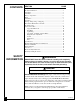
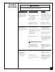
CONTENTS SECTION PAGE Safety Information ................................................................................ 2 Product Identification ........................................................................... 4 Unpacking ............................................................................................. 5 Assembly .............................................................................................. 5 Theory of Operation ....................................................
SAFETY INFORMATION Continued WARNINGS (Continued) • Use only kerosene or No. 1 fuel oil to avoid risk of fire or explosion. Never use gasoline, naphtha, paint thinners, alcohol, or other highly flammable fuels. • Fueling a) Personnel involved with fueling shall be qualified and thoroughly familiar with the manufacturer's instructions and applicable regulations regarding the safe fueling of heating units. b) Only the type of fuel specified on the heater's data plate shall be used.
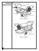
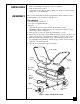
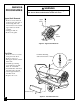
PRODUCT IDENTIFICATION Hot Air Outlet Upper Shell Lower Shell Fuel Cap Fan Guard Fuel Tank Side Cover Flame-Out Control Reset Button Power Cord Figure 1 - 150,000 Btu/Hr Thermostat Knob Figure 2 - 150,000 Btu/Hr 4 102384
UNPACKING ASSEMBLY 1. Remove all packing items applied to heater for shipment. 2. Remove all items from carton. 3. Check items for any shipping damage. If heater is damaged, promptly inform dealer where you bought heater. These models are furnished with wheels and handles. Wheels, handles, and the mounting hardware are found in the shipping carton. Tools Needed • Medium Phillips Screwdriver • 3/8" Open or Adjustable Wrench • Hammer 1. Slide axle through wheel support frame. Install wheels on axle.
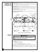
THEORY OF OPERATION The Fuel System: The air pump forces air through the air line. The air is then pushed through the burner head nozzle. This air causes fuel to lift from the tank. A fine mist of fuel is sprayed into the combustion chamber. The Air System: The motor turns the fan. The fan pushes air into and around the combustion chamber. This air is heated and provides a stream of clean, hot air. The Ignition System: The electronic ignitor sends voltage to the spark plug.
VENTILATION WARNING Follow the minimum fresh, outside air ventilation requirements. If proper fresh, outside air ventilation is not provided, carbon monoxide poisoning can occur. Provide proper fresh, outside air ventilation before running heater. Provide a fresh air opening of at least 2800 square cm (three square feet) for each 100,000 Btu/Hr rating. Provide extra fresh air if more heaters are being used. Example: A 150,000 Btu/Hr heater will require at least 4,200 square cm (4.
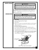
OPERATION Continued To Stop Heater 1. Unplug power cord from outlet. To Restart Heater 1. Wait 2 minutes after stopping heater. 2. Repeat steps under To Start Heater, page 7. STORING, TRANSPORTING, OR SHIPPING Note: If shipping, transport companies require fuel tanks to be empty. 1. Drain fuel tank. Note: Some models have drain plug on underside of fuel tank. If so, remove drain plug to drain all fuel. If heater does not have drain plug, drain fuel through fuel cap opening. Be sure all fuel is removed.
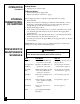
TROUBLESHOOTING WARNING Never service heater while it is plugged in, operating, or hot. Severe burns and electrical shock can occur. OBSERVED FAULT POSSIBLE CAUSE REMEDY Heater ignites, but flame-out control shuts off heater after a short period of time. Wrong pump pressure See Pump Pressure Adjustment, page 12. Dirty air output, air intake, and lint filters Dirty fuel filter See Air Output, Air Intake and Lint Filters, page 12. See Fuel Filter, page 10. Dirt in nozzle See Nozzle, page 13.
SERVICE PROCEDURES WARNING Never service heater while it is plugged in, operating, or hot. Severe burns and electrical shock can occur. Upper Shell Removal Upper Shell 1. Remove screws and lock washers along each side of heater using 5/16" nutdriver. These screws attach upper and lower shells together. 2. Lift upper shell off. 3. Remove fan guard. Fan Guard Figure 6 - Upper Shell Removal Fuel Filter 1. Remove side cover screws using 5/16" nut-driver. 2. Remove side cover. 3.
Spark Plug 1. Remove upper shell (see page 10). 2. Remove fan (see page 15). 3. Remove spark plug wire from spark plug. 4. Remove spark plug from burner head using 13/16" open-end wrench. 5. Clean and regap spark plug electrodes as follows: 2.8 mm (0.110") gap 6. Install spark plug in burner head. 7. Attach spark plug wire to spark plug. 8. Replace fan (see page 15). 9. Replace fan guard and upper shell.
Air Output, Air Intake, and Lint Filters 1. Remove upper shell (see page 10). 2. Remove filter end cover screws using 5/16" nutdriver. 3. Remove filter end cover. 4. Replace air output and lint filters. 5. Wash or replace air intake filter (see Preventative Maintenance Schedule, page 8). 6. Replace filter end cover. 7. Replace fan guard and upper shell.
Nozzle 1. Remove upper shell (see page 10). 2. Remove fan (see page 15). 3. Remove fuel and air line hoses from burner head. 4. Remove spark plug wire from spark plug. 5. Remove spark plug from burner head using 13/16" open-end wrench. 6. Remove three screws using 5/16" nut-driver and remove burner head from combustion chamber. 7. Place burner head into vise and lightly tighten. 8. Carefully remove nozzle from burner head using 5/8" socket wrench (see Figure 14). 9.
Pump Rotor Blade (Procedure if rotor is binding) 1. Remove upper shell (see page 10). 2. Remove filter end cover screws using 5/16" nutdriver. 3. Remove filter end cover and air filters. 4. Remove pump plate screws using 5/16" nutdriver. 5. Remove pump plate. 6. Remove rotor, insert, and blades. 7. Check for debris in pump. If debris is found, blow out with compressed air. 8. Install insert and rotor. 9. Check gap on rotor. Adjust to .076/.101 mm (.003"/.004") if needed (see Figure 16).
Fan IMPORTANT: Remove fan from motor shaft before removing motor from heater. The weight of the motor resting on the fan could damage the fan pitch. Fan Setscrew 1. Remove upper shell (see page 10). 2. Use 1/8" allen wrench to loosen setscrew which holds fan to motor shaft. 3. Slip fan off motor shaft. 4. Clean fan using a soft cloth moistened with kerosene or solvent. 5. Dry fan thoroughly. 6. Replace fan on motor shaft. Place fan hub flush with end of motor shaft (see Figure 19). 7.
ILLUSTRATED PARTS BREAKDOWN 2 18 1 150,000 Btu/Hr Model 3 4 5 8 12 13 14 7 9 15 8-1 10 8-2 11 17 30 8-4 31 8-5 46 25 26 8-3 8-7 24 29 18 33 34 36 22 18 19 44 8-6 27 32 23 21 20 28 35 47 37 Burner Head Assembly 48 47 49 38 39 16 45 42 13-1 13-2 41 13-3 13-4 13-5 40 43 13-6 6 13-7 13-18 13-8 13-17 13-16 13-15 13-9 13-10 13-14 13-11 13-13 16 Motor and Pump Assembly 13-12 102384
PARTS LIST 150,000 Btu/Hr Model This list contains replaceable parts used in your heater. When ordering parts, be sure to provide the correct model and serial numbers (from the model plate), then the part number and description of the desired part. KEY NO.
WHEELS AND HANDLES KEY PART NO. NUMBER 1 2 3 4 5 6 7 HA2204 M12345-33 M12831-3 NTC-3C 097896-04 M28526 M16801-2 PART DESCRIPTION QTY.
WIRING DIAGRAMS 220V~/50Hz WIRING DIAGRAM Thermostat Brown Blue White Motor Orange Ignitor Green-Yellow Green-Yellow Spark Plug White Terminal Board White Blue Purchase this accessory from your local dealer. Blue B FlameOut Control Reset Button Photocell Red Red Red ACCESSORY Black Green-Yellow R 098227-84 AIR GAUGE KIT - HA1180 For all models. Special tool to check pump pressure. EC CONFORMITY DECLARATION EC CONFORMITY DECLARATION DESA Europe B.V.
WARRANTY AND REPAIR SERVICE CERTIFICATE OF GENERAL EQUIPMENT - LIMITED ONE YEAR WARRANTY DESA International warrants new Products sold by it to be free from defects in material or workmanship for a period of one (1) year after date of delivery to the first user and subject to the following conditions: DESA International's obligation and liability under this Warranty is expressly limited to repairing or replacing at DESA International's option, any parts which appear to DESA International upon inspection to