OPERATING GUIDE for your Gemini C-Series System and the GEMC-FK1 KEYPAD COMMERCIAL FIRE SYSTEM © NAPCO 2011 OI341A 11/11 1
INTRODUCTION The GEMC-FK1 is the Primary Operator Interface for the fire section of your GEMC Combination Commercial Fire and Burglary Alarm System. It meets the requirements of NFPA and UL864 (9th Edition) as the Primary User Interface. When the system is operating normally without alarms, supervisory conditions or troubles, the keypad displays "SYSTEM NORMAL" and the AC ON indicator will be turned on.
T AB L E O F C O N T E N T S TABLE OF CONTENTS Section Page INTRODUCTION ....................................................................... 2 KEYPAD CONTROLS & INDICATORS ..................................... 4 NORMAL DISPLAY ................................................................... 6 FIRE ALARM DISPLAY ............................................................. 7 SUPERVISORY SIGNAL DISPLAY .......................................... 8 SYSTEM TROUBLE DISPLAY .................................
K E Y P AD C O N T R O L S & I N D I C AT O R S 2 1 3 4 5 6 11 7 12 8 13 9 10 4 14 COMMERCIAL FIRE SYSTEM 15
K E Y P AD C O N T R O L S & I N D I C AT O R S 1) LCD 32 Character Display: Displays system status, zone descriptions, menu options, etc. 2) SUPV Icon: Pulsing indicates Supervisory Signal; Steady indicates an acknowledged supervisory signal; Off indicates no supervisory signal. 3) 4) 5) TROUBLE Icon: Pulsing indicates a trouble; Steady indicates an acknowledged trouble; Off indicates no troubles.
N O R M AL D I S P L AY SYSTEM NORMAL 11/01/12 12:05 AM When the system is "normal", with no fire alarms, supervisory signals or troubles detected the system: 1. The red FIRE LED is off. 2. The Green AC ON LED is on. 3. The SUPV, TROUBLE, DISABLED and SILENCED icons are off. 4. The LCD displays "SYSTEM NORMAL" and date ("DD/MM/YY") and the time.
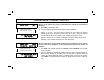
F I R E AL AR M D I S P L AY FIRE Z123 001 11/01/12 12:05 AM Display slowly scrolls between these two screens 123-SMK NW STAIR 3RD FLOOR When a single fire alarm is detected by the system: 1. The red FIRE LED will flash, and 2. The LCD display will slowly toggle between the following two displays: Display 1, top row: The word "FIRE" followed by the 3-digit zone # "ZXXX" (where XXX represents numbers from 001 to 255).
S U P E R V I S O R Y S I G N AL D I S P L AY SUPV. SUPV Z137 001 When a single supervisory signal is detected by the system (no fire alarms or troubles): 1. The SUPV icon will flash, and Display slowly scrolls between these 2 screens SUPV. 137-WATERFLOW SUPV 3RD FLOOR 2. The LCD display will slowly toggle between the two displays: Display 1, top row: The word "SUPV" followed by the 3-digit zone number "ZXXX" (where XXX represents numbers from 001 to 255).
SYSTEM TROUBLE DISPLAY SUPV. SYStrbl E02 001 11/01/12 12:05 AM When a single system trouble is detected by the system (no fire alarms, or supervisory alarms): 1. The TROUBLE icon will flash, and 2. The LCD display will slowly toggle between the two displays: Display slowly scrolls between these 2 screens SUPV. LOW BATTERY E02-000 Display 1, top row: "SYStrbl" followed by "EXX" where XX represents the specific error code of the associated trouble, numbers from 01 to 99.
U N L O C K I N G T H E K E Y P AD * SYSTEM NORMAL 11/01/12 12:05 AM KEYPAD LOCKED ENTER CODE Only persons with authority may "unlock" the keypad, allowing them to affect the operation of the Fire alarm system. This authority is determined either by a valid 4- through 6-digit "User Code" or by the use of a momentary or maintained key switch mounted adjacent to the keypad. Also see note below and ask your Dealer how the system is programmed.
S I L E N C I N G A N D R E S E T T I N G A F I R E AL A R M FIRE Z123 001> 11/01/12 12:05 AM When a fire alarm is detected by the system, the keypad must be "unlocked" to view the total system status, silence audible alarms and reset the system (see Unlocking the Keypad on page 10). 123-SMK NW STAIR 3RD FLOOR Press the ACK. button to acknowledge the fire alarm and silence the local keypad sounder. The Fire alarm LED will change from flashing to steady.
S I L E N C I N G A N D R E S E T T I N G F I R E AL AR M FIRE Z123 001 11/01/12 12:05 AM After the entire system status has been reviewed using the NEXT and PRIOR buttons and the authority on site reaches the reasonable decision to silence the alarm sounders, proceed as follows: 123-SMK NW STAIR 3RD FLOOR Press SILENCE to silence all audible fire alarm sounders. All sounding appliances will silence and the SILENCED icon will turn on steady.
FIRE PROTECTION LIMITATIONS OF FIRE ALARM WARNING SYSTEM Although a fire alarm system may be of a reliable and state-of- the-art design, neither it nor its peripheral detection devices can offer guaranteed protection against fire. Any such equipment may fail to warn for a variety of reasons: Control panels, communicators, dialers, smoke detectors, and many other sensing devices will not work without power.
E V AC U A T I O N P L AN N I N G Assign responsibility for the following tasks: 1. Determine the best evacuation routes, and contingency routes. 2. Determine the best emergency assembly areas, and evaluate the safety of these assembly areas. 3. Determine how to disseminate information about the selected evacuation routes and assembly areas. 4. During an alarm, select personnel who will be responsible for ensuring the evacuation routes are clear. 5.
F AM I L Y E M E R G E N C Y P L A N N I N G Protect yourself by planning ahead. The following checklist will help you get started. Discuss these ideas with others, and then prepare an emergency plan. Post the plan where everyone will see it. • Meet with household members to discuss the dangers of fire, severe weather, earthquakes and other emergencies. Explain how to respond to each. • Find the safe spots in your home for each type of disaster.
FUNCTION MENU The keypad can provide access to a wide assortment of utility functions. 1. To enter the Function Menu, first unlock the keypad (see Unlocking the Keypad on page 10) then press MENU. 2. To skip a function, press MENU. 3. To select and execute a function, press ENTER or NEXT. • Functions may be manually scrolled forward or backward using MENU and SILENCE, respectively. • To return to normal keypad operation, press RESET.
FUNCTION MENU (cont'd) Y/N LOCK KEYPAD: Master Security Code or Dealer Keypad Program Code or Fire User Code required to view this function) Immediately locks keypad. Must unlock with key or code to affect system operation. DISPLAY FIRE LOG Y/N DISPLAY FIRE LOG: Displays all fire events in chronological order; use NEXT and PRIOR buttons to scroll through the log. Refer to page 27 for the Fire Log event descriptions.
FUNCTION MENU (cont'd) ENTER CODE TO CHANGE (ENTER) number of Fire User Codes in a system is determined by the number of codes added within PCD-Windows Quickloader download software. Change an existing Fire User Code: 1. ENTER NEW CODE 2. 3. RE-ENTER NEW CODE SYSTEM READY 11/01/12 12:09 AM 4. As detailed at the beginning of this section, press MENU until this "ENABLE (CHANGE USER CODE)" selection appears, then press NEXT/YES. The keypad display reads: "ENTER CODE TO CHANGE (ENTER)".
FUNCTION MENU (cont'd) CF DEALER PROG MODE ENABLE PROGRAMMING Y/N Y/N Execute Download Y/N Supplemental Output Reset DISPLAY RF XMITTER STAT Reinitialize FSLC Devices Y/N Y/N Y/N CF DEALER PROGRAM MODE? (Master Security Code or Dealer Keypad Program Code required to view this function). Allows dealer to change system programming.
FUNCTION MENU (cont'd) valid communication and correct operation for each Fire SLC device in the system. When initiated, power is removed from the GEMC-FW-SLC bus (the common pathway that connects all of the Fire SLC devices), then power to the GEMC-FWSLC bus is restored. Each device's pre-existing configuration (stored within each device) is retained.
FUNCTION MENU (cont'd) Disable Remote Reporting Y/N DISABLE REMOTE REPORTING? (Master Security Code or Dealer Keypad Program Code required to view this function). Simplifies Dealer servicing and downloading program changes by disabling all Fire and Burglary reporting. When disabled, the option "Enable Remote Reporting" will appear. Note: Exiting Dealer Program Mode will re-enable remote reporting.
DO FIRE DRILL A fire drill is a pre-planned rehearsal designed to test the fire alarm system and evacuation procedures. Before performing a fire drill, always notify the central monitoring station and/or fire department to ensure that the alarm report was actually received and to avoid an unintentional response by fire personnel.
O N E M AN T E S T DO ONE MAN TEST Fire Watch A fire watch is implemented to ensure the fire-safety of a building or an area in the event of any act (such as entering One Man Test mode) that creates an increased risk to persons or property. The term "Fire Watch" is used to describe a dedicated person or persons whose sole responsibility is to look for fires within an established area.
C E N T R AL S T A T I O N M O N I T O R I N G Your alarm specialist has programmed your system to be monitored by a central station. The digital communicator can transmit emergency signals and status reports to the central station 24 hours a day. Fire Communicator Features Test Timer. Will send a signal to the central station once a day over telephone lines or once a minute over the internet. This feature is always enabled and cannot be turned off.
K E Y P AD M E S S AG E S The keypad can display the following functional messages. Other diagnostic messages are available for the installer or servicer. Should any unfamiliar messages appear, call your dealer for service. SYSTEM NORMAL (DATE) (TIME) INVALID ENTRY TRY AGAIN AC POWER FAIL E01-00 SERVICE System operating normally with no fire alarms, supervisory signals or troubles. Wrong code entered. Check for blown fuse or circuit breaker; general power outage. Battery weak.
G L O S S AR Y Following are brief descriptions of terms and features used herein that may be unfamiliar to you. Some of the features are programmable options that may or may not apply to your particular system. Battery - Backup power source in the control-panel enclosure to provide protection in the event of a power failure. Central Station - Monitors incoming reports and emergency m essa ges f rom a digital communicator and notifies the proper authorities.
FIRE LOG Displays a list of all Fire events that have occurred within the system. The information displayed includes an event number, the device number, device location, date, time and the following event "type" descriptions: Fire: System in Fire alarm. Fire Rstor: System restored from Fire alarm. Fire Tbl: Fire trouble detected on system. FrTbl Rstr: System restored from Fire trouble; Fire trouble removed. CleanSmks: Smoke detector issued a request for cleaning.
SYSTEM TROUBLE ERROR CODES Your control panel is capable of detecting a variety of troubles that may affect system performance. If a trouble is detected, the TROUBLE icon will flash on the left side of keypad window along with one or more of the following error codes. If the problem is related to a specific zone or device, the corresponding number will also be indicated. Below is a list of the most common troubles along with the necessary corrective action, if any.
SYSTEM TROUBLE ERROR CODES TBL # FIRE KEYPAD DISPLAY KEYPAD TROUBLE DESCRIPTION E03-00 SYStrbl E03 xxx MM/DD/YY HH:MM ' Comm Failure ' 'E03-000 SERVICE ' Communication Failure: The system was not able to report to the central station. If this is due to a temporary interruption in the telephone service, the trouble can be cleared when the service is restored by performing a Communication Test: Fire Keypads 1. Enter code to unlock keypad and press MENU. 2.
SYSTEM TROUBLE ERROR CODES TBL # E07-00 E08-NN E09-00 E14-NNN E15-NNNNNN E16-NN E17-NN 30 KEYPAD TROUBLE DESCRIPTION FIRE KEYPAD DISPLAY 'Download Failure' 'E07-00 SERVICE' SYStrbl E08 xxx MM/DD/YY HH:MM 'Telco Line Fail ' 'E08-NNN SERVICE ' SYStrbl E09 xxx MM/DD/YY HH:MM ' COLD START ' 'E09-000 SERVICE ' SYStrbl E14 xxx MM/DD/YY HH:MM 'NacRly BoardTrbl' 'E14-000 SERVICE ' SYStrbl E15 xxx MM/DD/YY HH:MM 'RFpnt Tamper' 'E15-NNN XXXXXX' SYStrbl E16 xxx MM/DD/YY HH:MM 'RFRec JammedTrbl' 'E16-000 SERVIC
SYSTEM TROUBLE ERROR CODES TBL # FIRE KEYPAD DISPLAY E19-00 'SystemMemoryFail' 'E19-00 SERVICE' Internal User Program memory error. Fire Keypads: Unlock keypad and press RESET to clear. Burg Keypads: Select menu option RESET SYSTEM TBL then press ENTER. E20-00 SYStrbl E20 xxx MM/DD/YY HH:MM 'Panel Memory ERR' 'E20-000 SERVICE ' Internal Program memory error. Fire Keypads: Unlock keypad and press RESET to clear. Burg Keypads: Select menu option RESET SYSTEM TBL then press ENTER.
SYSTEM TROUBLE ERROR CODES TBL # E31-NNN E32-00 E33-NNN E35-NNN E59-00 E66-00 32 FIRE KEYPAD DISPLAY SYStrblE31 xxx MM/DD/YY HH:MM 'FireEzmNoRespTbl' 'E31-NN SERVICE ' SYStrbl E32 xxx MM/DD/YY HH:MM 'Fire Keypad Trbl' 'E32-NNN SERVICE ' SYStrbl E33 xxx MM/DD/YY HH:MM 'FireEzm Tamper' 'E33-000 SERVICE ' RlyTbl/ E35 NN MM/DD/YY HH:MM NN-XXXXXXXXXXXX XXXXXXXXXXXXXXXXX SYStrbl E59 xxx MM/DD/YY HH:MM 'Tcpip Comm Fail ' 'E59-NNN SERVICE ' SYStrbl E66 xxx MM/DD/YY HH:MM 'CleanSmk' 'E66-NNN XXXXXX' KEYPAD
SYSTEM TROUBLE ERROR CODES TBL # E72-00 E90-00 E91-00 E92-000 E94-000 E96-000 FIRE KEYPAD DISPLAY SYSTrbl E72 xxx MM/DD/YY HH:MM 'RFRec High Noise' 'E72-000 SERVICE ' SYStrbl E90 xxx MM/DD/YY HH:MM 'FslcRec Mem Fail' 'E90-000 SERVICE ' SYStrbl E91 000 MM/DD/YY HH:MM 'NLM SUPV TROUBLE' 'E91-000 SERVICE ' SYStrbl E92 xxx MM/DD/YY HH:MM 'FslcRec Unmapped' 'E92-000 SERVICE ' SYStrbl E94 xxx MM/DD/YY HH:MM 'FslcRec NoRespon' 'E94-000 SERVICE ' SYStrbl E96 xxx MM/DD/YY HH:MM 'FslcRec LoopTrbl' 'E96-000 SER
SYSTEM TROUBLE ERROR CODES TBL # KEYPAD TROUBLE DESCRIPTION FIRE KEYPAD DISPLAY Trouble detected on a Fire SLC device. Each device generates troubles specific to its Type (see list numbered 1-9 below) and all troubles are indicated with this trouble except the E66 "CleanSmk" sensitivity trouble. NNN is the associated zone number; XXXXXX is the Device Six-Character ID number (the second number from left is the "Type" as per the list below).
SLC ZONES SLC Loop 1 Zone No. SLC Loop 1 Description Zone No. SLC Loop 1 Description Zone No.
SLC ZONES SLC Loop 1 Zone No. 36 SLC Loop 1 Description Zone No. SLC Loop 1 Description Zone No.
SLC ZONES SLC Loop 2 Zone No. SLC Loop 2 Description Zone No. SLC Loop 2 Description Zone No.
SLC ZONES SLC Loop 2 Zone No. 38 SLC Loop 2 Description Zone No. SLC Loop 2 Description Zone No.
NOTES 39
NAPCO LIMITED WARRANTY NAPCO SECURITY SYSTEMS, INC. (NAPCO) warrants its products to be free from manufacturing defects in materials and workmanship for thirty-six months following the date of manufacture. NAPCO will, within said period, at its option, repair or replace any product failing to operate correctly without charge to the original purchaser or user.