
- Master Portable Gasoline Generator Owner's Operation And Installation Manual

16
117846
PORTABLE GASOLINE GENERATORS
R
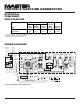
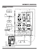
WIRING DIAGRAMS
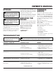
Resistance in Ohms
Stator Stator Rotor Capacitor,
Main Auxiliary Primary MFD Diodes (2)
Model Winding * Winding
Δ Winding † 450 Volt 800 Volt
MGH8500AIE 0.41 .098 7.81 45 8 Amp
MGH10000C 0.33 0.71 8.53 60 8 Amp
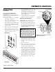
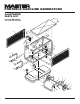
ELECTRICAL
COMPONENT
SPECIFICATIONS
*
Connect T2 (green) and T3 (black). Measure resistance between T1 (red) and T4 (yellow).
Δ
Resistance between brown and white leads.
†
Remove diodes to check resistance.
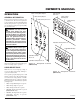
Figure 22 - Wiring Diagram, Model MGH10000C
250V 30A
Receptacle
250V 50A
Receptacle
125V, 15A
Receptacle
GFCI 125V, 15A
Receptacle
125V, 30A
Receptacle
Circuit
Breaker
20A
Circuit
Breaker
20A
Green
Green
Black
Black
White
Black
Red
Black
Black
Black Black
Black
Gray
Gray
Gray
Gray
Gray
Blue
Blue
White
Green
Black
Black
Black
Red
Red
Red
Red
Yellow
Yellow
Auto-Idle
Control Board
Yellow
WhiteWhite
White
Circuit
Breaker
30A
Circuit
Breaker
30A
Circuit
Breaker
45A
Circuit
Breaker
45A
Green
T2
Green
Black
Red
White
Main
Windings
T1
T3
T4
Wh
T1 T2T3T4
Rotor
Diode
Diode
Stator
Capacitor
White
White
Run
Light
Hour Meter
Gr
een
P2
P5
P5-2
P5-4
P5-1
P5-3
P1
P4
P3
To
Auto-Idle
Solenoid
To
Power Supply
On Engine
Stator
110/120V
T1 T2 T3 T4
L2
L1
110/120V
220/240V