
Service manual


This power supply is designed to be permanently connected to the power source requiring a
readily accessible disconnect device incorporated into the fixed wiring.
2.3 DC Output Connections
Caution: disconnect AC power from the mains before attempting any
installation procedure.
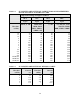
Table 2.1 SUGGESTED AMPACITIES OF 4-CONDUCTOR
TYPE S OR SO CABLE
Wire Size
(AWG)
Maximum
Current
(A)
Wire Size
(AWG)
Maximum
Current
(A)
18
16
14
12
10
7
10
15
20
25
8
6
4
2
35
45
60
80
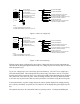
DC power is wired to the power supply by attaching two cables to the output bus bars. The
manufacture recommends cables, as specified in Tables 2.2 or 2.3, be crimped to ring terminals
and securely fastened to bus bars using 3/8" bolts, washers, and lock washers. The bus bars
contain 3/8-16 threaded inserts. After connections are made, screw the four standoffs into the
back panel and place the protective shield over the connections.
Caution: Make sure connections are tight to avoid overheating of the bus bars.
2.4 General Operation
As shipped, XR and XRC Series power supplies are configured for local sensing, rotary control,
internal programming, and voltage input as specified on the rear label. XRC Series power
supplies are configured for RS232, optional IEEE-488, or optional Ethernet communications.
The front panel voltage and current controls set the boundary limits for output voltage and
current, respectively. The impedance of the load determines whether the unit is voltage or
current controlled and the illumination of the respective mode indicator lights indicate the state.
If either control is set to maximum counter clockwise rotation, the other control will have little
or no effect. Each control must be set to the appropriate position for proper operation.
19