
Service manual


3.0 OPERATION
3.1 Front Panel Commands
As shipped, the XR Series power supply is configured for local sensing, rotary control, internal
programming, and voltage input as specified on the rear label. XRC Series power supplies
cannot be controlled through the front panel other than on/off. The front panel voltage and
current controls set the boundary limits for output voltage and current, respectively. Section
2.6.2 describes how to start and operate the XR Series power supply using the default settings.
The following sections describe how to use all of the front panel features. Front panel
commands are broken into four groups: run mode commands, set point commands, configuration
commands, and calibration commands.
Run mode commands are used when the power supply has been configured for the desired
application and the desired set points have been programmed into memory.
Set point commands include voltage set, current set, over voltage trip set, and over current trip
set. All of these commands can be made when the power supply is in either the standby, alarm,
or power mode state.
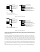
Configuration commands include local or remote sense, internal and/or external control, remote
interlock, and mode of set point input. There are three choices for set point inputs: rotary or
front panel potentiometers, external analog through connector JS1, and RS232 communications
through connector JS3, optional IEEE-488 communications through connector JS4, and optional
Ethernet communications through JS5. Changes in configuration commands are only allowed
when the power supply is in the standby or alarm state.
Calibration commands enable programming of internal digital potentiometers. The digital
potentiometers are used for calibrating the voltage reference and feedback amplifiers.
Calibration commands can be made when the power supply is in either the standby, alarm, or
power mode state.
Front panel programming commands are illustrated with programming charts. This method of
presentation maps the path to key commands, describes front panel indicators as a result of key
presses, and illustrates anticipated results.
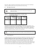
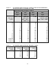
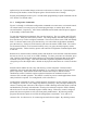
3.1.1 Run Mode Commands
Figure 3.1 illustrates run mode commands. Run mode commands are used when the power
supply has been configured for the desired application.
25