
Service manual

which is actively applied to the modulation function. With Loc set to 1, data will be stored to the
Cache Table, the table intended to be accessed in the next in the profile. During the power on
cycle, modulation tables stored in EPROM are copied into volatile RAM. Additional SCPI
commands related to data storage and table transfers are described in Sections 4.3.14.3 and
4.3.14.4.
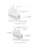
Modulation linearly interpolates between data points to form a piecewise-linear curve. Each
column has to have data in an acceptable range. All tables less than 50 rows must be terminated
with a VMOD value of 9999. Mod values at and past a row with VMOD of 9999 does not affect
modulation.
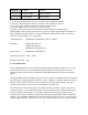
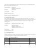
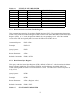
TABLE 4.4 MODULATION TABLE PARAMETERS
Column
12 3 4
Description Row VMOD Mod Loc
Acceptable Range 1 to 50 0.0 TO 10.0 -1000.0 to 1000.0 0 to 1
While the table will store any value within the acceptable range, the power supply is limited by its
output voltage and current specifications. For example, when using type 1 modulation,
MOD:TYPE:SEL 1,1, a user can store a Mod value of -1000, but the power supply will only
output a voltage down to 0 V.
Modulation points are read with two comma separated parameters, formatted as:
Row, Loc. The query will return four parameters, formatted in the same way as the save table
command above.
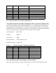
Command Syntax: MOD:TABL <NR1>(<NRf>,<NRf>,<NR1>)
Examples: MOD:TABL 12(0.13, 1.6, 1)
MODulation:TABLe 20(2.0, 15.002, 0)
MOD:TABL 13(1.5, -1.29, 0)
MOD:TABL 14(9999, 0, 1)
Query Syntax: MOD:TABL? <NR1>,<NR1>
Returned Parameters: <NR1>(<NRf>,<NRf>,<NR1>)
Related Commands: None
4.3.14.3 MOD:SAVE
This command copies the Active Table in RAM to a non-volatile, EEPROM memory. The Active
72