
Instruction manual

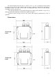
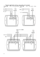
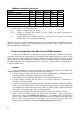
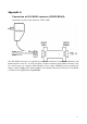
Table Of Contents
Instruction Manual for use of transducer:
TE232-102D (RS232), TE485-102D (RS485)
Transducer is designed for temperature measurement at °C or °F by means of the external
temperature probe with RTD Pt1000 sensor. It is built in a plastic case with the IP65 protection.
Read this manual before the first transducer connection. Transducer TE232-102D communicates
via link RS232, transducer TE485-102D via link RS485. Supported communication protocols are
Modbus RTU, protocol compatible with standard Advantech-ADAM and ARION. Measured value
is displayed on dual line LCD display. Display can be also switched OFF. Output link RS485 of
transducer TE485-102D is galvanic isolated. Output link RS232 of transducer TE232-102D is
NOT galvanic isolated. Please read instruction manual before the first device connection.
Use user’s software Tsensor for setting of all device parameters (recommended). It
supports make the adjustment of the device too. This procedure is described at file „Calibration
manual.pdf“ which is installed commonly with the software. Change of some parameters is possible
to do without user’s software with Windows hyperterminal (change of communication protocol, its
parameters, LCD display setting).
Transducer setting from the manufacturer
If special setting was not required in the order, transducer is set from the manufacturer to the
following parameters:
communication protocol: Modbus RTU
transducer address: 01H
communication speed: 9600Bd, no parity, 2 stop bits
display: switched ON
Transducer installation
Transducer is designed for wall mounting. There are two mounting holes at the sides of the
case. Don’t connect transducer while power supply voltage is on. Interconnection terminals are
accessible after unscrewing four screws and removing the lid. Lace the cable through a gland at the
case wall. Connect the cable to terminals with respecting the signal polarity (see figure). Terminals
are self-clamping and can be opened by a suitable screwdriver. For the opening, insert the
screwdriver to smaller terminal hole and lever by him. Do not forget to tighten glands and case lid
with inserted packing after cables connecting. It is necessary for warranting of protection IP65.
Working position is negligible.
External temperature probe should be of „shielded two-wire“ type. For leading of the cable
same recommendations are valid as for current loop cable, i.e. cable should be located as far as
possible from potential interference sources. Maximum probe cable length is 10 m. Connect probe
cable shielding to proper terminal and do not connect it to any other circuitry and do not ground it.
If connected probe is equipped with metal stem, we recommend to use probes with metal stem not
connected to cable shielding. Or else it is necessary to arrange metal stem is not connected to any
other circuitry.
Transducer TE232-102D is supplied with connection cable equipped with connector for
connection to RS232 interface. For TE485-102D transducer (RS485) it is recommended to use
shielded twisted copper cable (e.g. SYKFY ). Outside diameter of the cable must be from 3 to 6.5
mm, maximal length 1200m. The cable must be located at indoor rooms.
Nominal cable impedance should be 100 Ω, loop resistance max. 240 Ω, cable capacity max.
65 pF/m. Suitable cable is e.g. SYKFY 2x2x0,5 mm
2
, where one wire pair serves for transducer
powering and the other pair for communication link.
2
2