PORTABLE FORCED AIR HEATER (WITH BUILT-IN THERMOSTAT) OWNER’S MANUAL 50 SIDE Heater Sizes: 70,000 110,000 150,000 and 165,000 Btu/Hr IMPORTANT Read and understand this manual before assembling, starting, or servicing heater. Improper use of heater can cause serious injury. Keep this manual for future reference.
70,000 110,000 150,000 AND 165,000 BTU/HR PORTABLE FORCED AIR HEATER SAFETY INFORMATION WARNINGS IMPORTANT: Read this Owner’s Manual carefully and completely before trying to assemble, operate, or service this heater. Improper use of this heater can cause serious injury or death from burns, fire, explosion, electrical shock, and carbon monoxide poisoning.
OWNER’S MANUAL PRODUCT IDENTIFICATION UNPACKING 1. 70,000 Btu/Hr Model Hot Air Outlet 2. 3. Upper Shell Lower Shell Remove all packing items applied to heater for shipment. Remove all items from carton. Check items for shipping damage. If heater is damaged, promptly inform dealer where you bought heater.
70,000 110,000 150,000 AND 165,000 BTU/HR PORTABLE FORCED AIR HEATER ASSEMBLY 2. The 110,000 150,000 and 165,000 Btu/Hr models are furnished with wheels and handle(s). Wheels, handle(s), and the mounting hardware are found in the shipping carton. 3. TOOLS NEEDED 4. • Medium Phillips Screwdriver • 3/8" Open or Adjustable Wrench • Hammer 1. Slide axle through wheel support frame. Install wheels on axle.
OWNER’S MANUAL THEORY OF OPERATION OPERATION WARNING: Review and understand the warnings in the Safety Information section, page 2. They are needed to safely operate this heater. Follow all local codes when using this heater. The Fuel System: The air pump forces air through the air line. The air is then pushed through the burner head nozzle. This air causes fuel to lift from the tank. A fine mist of fuel is sprayed into the combustion chamber. The Air System: The motor turns the fan.
70,000 110,000 150,000 AND 165,000 BTU/HR PORTABLE FORCED AIR HEATER STORING, TRANSPORTING, OR SHIPPING Note: If shipping, transport companies require fuel tanks to be empty. 1. Drain fuel tank. Note: Some models have drain plug on underside of fuel tank. If so, remove drain plug to drain all fuel. If heater does not have drain plug, drain fuel through fuel cap opening. Be sure all fuel is removed. 2. Replace drain plug if provided. 3.
OWNER’S MANUAL TROUBLESHOOTING WARNING: Never service heater while it is plugged in, operating, or hot. Severe burns and electrical shock can occur. OBSERVED FAULT POSSIBLE CAUSE REMEDY Heater ignites, but flame-out control shuts off heater after a short period of time 1. Wrong pump pressure 2. Dirty air output, air intake and lint filters 1. See Pump Pressure Adjustment, page 9 2. See Air Output, Air Intake and Lint Filters, page 8 3. See Fuel Filter, page 9 4. See Nozzle, page 10 5.
70,000 110,000 150,000 AND 165,000 BTU/HR PORTABLE FORCED AIR HEATER FAN SERVICE PROCEDURES WARNING: Never service heater while it is plugged in, operating, or hot. Severe burns and electrical shock can occur. UPPER SHELL REMOVAL 1. 2. 3. Remove screws along each side of heater using 5/16" nut-driver. These screws attach upper and lower shells together. Lift upper shell off. Remove fan guard. Upper Shell Fan Guard IMPORTANT: Remove fan from motor shaft before removing motor from heater.
OWNER’S MANUAL SERVICE PROCEDURES Continued 2. 3. 4. 5. SPARK PLUG 1. 1. 2. 3. 4. 2. 3. 4. PUMP PRESSURE ADJUSTMENT 1. FUEL FILTER Remove pressure gauge plug from filter end cover. Install accessory pressure gauge (part number HA1180). Start heater (see Operation, page 5). Allow motor to reach full speed. Adjust pressure. Turn relief valve to right to increase pressure. Turn relief valve to left to decrease pressure. Correct Pump Pressure 70,000 Btu/Hr Model: 4.0 PSI 110,000 Btu/Hr Model: 4.
70,000 110,000 150,000 AND 165,000 BTU/HR PORTABLE FORCED AIR HEATER Nozzle Face SERVICE PROCEDURES Blade Nozzle Seal Pump Plate Air Intake Filter Continued Filter End Cover NOZZLE 1. 2. 3. 4. 5. 6. 7. 8. 9. 10. 11. 12. 13. 14. 15. 16. 17. Nozzle Remove upper shell (see page 8). Remove fan (see page 8). Remove fuel and air line hoses from burner head. Remove spark plug wire from spark plug. Remove spark plug from burner head using 13/16" open-end wrench.
OWNER’S MANUAL SPECIFICATIONS Output Rating (Btu/Hr.) Fuel Fuel Tank Capacity (U.S. Gal.) Fuel Consumption (Gal. Per Hr.) Electric Requirements Amperage (Normal Run) Hot Air Output (CFM) Motor RPM Motor HP Shipping Weight (Appox. lbs.) Heater Weight Without Fuel (Appox. lbs.) 70,000 110,000 150,000 Use Only Kerosene or No. 1 Fuel Oil 165,000 5.0 13.5 13.5 Note: Use only original replacement parts. This will protect your warranty coverage for parts replaced under warranty. 0.52 0.82 1.
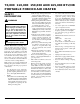
70,000 110,000 150,000 AND 165,000 BTU/HR PORTABLE FORCED AIR HEATER ILLUSTRATED PARTS BREAKDOWN 4 1 70,000 BTU/HR 2 5 3 9 6 7 8 21 10 12 16 15 Burner Head Assembly 26 9-1 11 41 19 13 20 22 17 9-2 23 24 33 34 9-3 9-4 25 30 9-7 9-5 32 31 35 18 9-6 28 27 14 47 12-1 12-2 29 46 12-3 12-4 12-5 36 45 40 12-6 12-7 12-18 12-17 38 39 37 12-8 12-16 12-9 12-10 12-15 43 12-11 12-14 Motor and Pump Assembly 42 44 12-13 12-12 12 103301
OWNER’S MANUAL PARTS LIST This list contains replaceable parts used in your heater. When ordering parts, be sure to provide the correct model and serial numbers (from the model plate), then the part number and description of the desired part. 70,000 BTU/HR KEY NO.
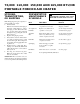
70,000 110,000 150,000 AND 165,000 BTU/HR PORTABLE FORCED AIR HEATER ILLUSTRATED PARTS BREAKDOWN 2 1 3 110,000 150,000 AND 165,000 BTU/HR 4 6 7 9 10 39 5 Burner Head Assembly 16 8 7-1 23 7-2 14 11 19 13 24 12 28 15 25 17 7-3 43 7-4 26 26 20 7-7 7-5 22 29 21 38 27 18 30 37 7-6 46 31 45 40 44 10-1 32 10-2 10-3 42 10-4 10-5 35 10-6 33 34 10-7 10-17 36 41 10-8 10-16 10-9 10-15 10-13 10-10 10-14 10-11 10-13 Motor and Pump Assembly 10-12 14 103301
OWNER’S MANUAL PARTS LIST 110,000 150,000 AND 165,000 BTU/HR This list contains replaceable parts used in your heater. When ordering parts, be sure to provide the correct model and serial numbers (from the model plate), then the part number and description of the desired part. KEY NO.
70,000 110,000 150,000 AND 165,000 BTU/HR PORTABLE FORCED AIR HEATER PARTS LIST WHEELS AND HANDLE PARTS LIST KEY PART NO. NUMBER 1 HA2203 HA2204 M12345-33 M12342-3 M12831-3 NTC-3C 097896-04 097896-01 M28526 M51015-01 M16801-2 2 3 4 5 6 7 110 MODEL QTY. PART DESCRIPTION Handle 2 (if equipped) Handles — Screw, #10-24 x 1 3/4" 8 Wheel Support Frame 1 Wheel Support Frame — Hex Nut, #10-24 8 Wheel (Black Hub) 2 Wheel (White Hub) 2 Cap Nut 2 Axle 1 Axle — 150/165 MODELS QTY.
OWNER’S MANUAL ACCESSORIES Purchase accessories and parts from your nearest dealer or service center. If they can not supply these accessories or parts, either contact your nearest Parts Central or DESA International for referral information. Parts Centrals are listed in the Authorized Service Center booklet supplied with heater. DESA International P.O.
WARRANTY AND REPAIR SERVICE LIMITED WARRANTY DESA International warrants this product and any parts thereof, to be free from defects in materials and workmanship for one (1) year from the date of first purchase when operated and maintained in accordance with instructions. This warranty is extended only to the original retail purchaser, when proof of purchase is provided. This warranty covers only the cost of parts and labor required to restore the product to proper operating condition.