Masterclock RC 500 User Manual – v2014.01.
Table of Contents The RC 500 is a remote control timer that adds count-down and count-up control to NTDS and TCDS digital display clocks. Introduction .................................................................................... 3 Installation ........................................................................................ 4 Wiring Solutions................................................................................ 5 Interface ............................................................
Introduction The RC500 is a programmable, single channel, timer control unit. It remotely communicates with TCDS or NTDS digital time displays, providing count-up, countdown and count-to capabilities.
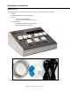
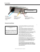
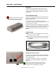
Unpacking and Installation Supplied (Ship Kit) The list below is for illustration purposes. Refer to your sales order for actual items shipped. RC500 CD-ROM (WinDiscovery and User Manual) Power o AC power cord with IEC plug o PoE uses the CAT5 Ethernet patch cable Communications o CAT5 Ethernet patch cable (NTDS series) o 6P6C modular cable (TCDS series) 4 Cat5 Ethernet patch cable || CD with user manual and software || AC power cord with IEC plug ____ Masterclock RC 500 User Manual – v2014.01.
Connections The back of the RC 500 with power and communication sockets IEC socket AC power (optional) This socket will not appear on NTP models RJ12 port RS485 communications (TCDS series digital time display) RJ45 port Ethernet communications (NTP series digital time display) PoE (optional) Network Installation 5 Some users will connect their RC500 to a network for external time reference. Others will use their RC500 ‘as is’ by simply plugging it in.
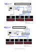
TCDS and NTDS digital display clocks 6 NTDS digital display clocks Masterclock RC 500 User Manual – v2014.01.
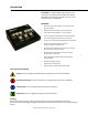
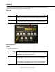
Interface The top panel provides immediate access to all major RC500 functions. The panel consists of a 6 digit, 7 segments LED display along with three sets of pushbuttons. Status LED The colons on the LED display are used to alert the user of lock to time reference. Colons Description Flashing Time is not able to be decoded from the time reference or the reference is not present. Time displayed on the face of the unit is based upon internal RTC and may not be accurate.
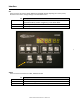
Interface Set There are three set buttons: HOUR, MINUTE and SECOND. Besides adjusting the counter preset, the buttons are used to change settings in the standalone menu. Set Description HOUR Select a preset of 0 – 24 hours. {Standalone Menu} Select a negative (-) Time Zone offset. MINUTE Select a preset of 0 – 59 minutes. SECOND Select a preset of 0 – 59 seconds. 8 Action There are three action buttons: START, PAUSE and STOP. Set START PAUSE STOP Description Initiate or resume the count routine.
Operation – Input/Output OVERVIEW The RC500 is a programmable, single-channel, timer control unit. The RC500 will communicate with single or multiple TCDS and NTDS digital time displays or it may stand alone. RS485 COMMUNICATION Do not connect more than one RC 500 to the same splitter. The RC500 can control up to six digital clocks. TCDS series of digital time displays are connected to the RC500 using the RJ12 port and a 6 wire (6P6C) straightthrough modular cable.
Control Button Details Control Button Detail THREE BUTTON SETS ON THE FACEPLATE The “MODE” set controls whether you want simple clock operation, count-up, or count-down. The “SET” set controls the hour, minute and second. The remaining (lower row) set starts, pauses and stops the other two modes. Examples The combination of LED display and illuminated buttons indicate the selected mode and current step being performed. There are four modes of operation.
During a routine, press [PAUSE] to freeze the running count. To continue, press [START] and the routine will continue from its paused count. To end a running count before its end number is reached; press [STOP] and the count will reset back to the preset (i.e. end number) and hold for the next command. Count-down Select the mode of operation by pressing the button labeled [DOWN]. Enter the start number (preset) by pressing the [HOUR], [MINUTE] or [SECOND] buttons.
COUNT TO TIME Select the “Count to Time” mode by pressing and holding the [DOWN] button for 2 seconds. The [DOWN] button should begin to steadily flash. Enter the end real time of the count up by pressing the [HOUR], [MINUTE] and/or [SECOND] buttons. With each corresponding button pressed, the digit on the display will increment. Enter the Real Time that you want to the display to count-down toward in a 24 hour timescale. (e.g.
Custom Time Menu There are situations where the end-user needs to display time differently than from a time reference. When the custom time is used, the time displayed will not have Time Zone offsets or DST applied. However the time can be displayed in 12 or 24 hour format. Please refer to “Standalone Menu Display Properties” in the previous section of this document for configuration of display settings. To use the custom time feature, any external time reference (i.e.
Standalone Menu Display Properties The RC500 can be customized to display time in a variety of formats and brightness levels. To enter the configuration menu press and hold [CLOCK] for approximately 2 seconds. Press [DOWN] to cycle through the configuration menu. Press [HOUR], [MINUTE] and [SECOND] to change settings. Press [CLOCK] to exit the configuration menu. Each menu setting will be saved until a user makes a change to the setting or the unit is reset to factory default.
Time Display Format The unit can display time in 24 or 12 hour formats. When set to 12 hour format, the AM/PM indicator will be on during the PM hours. :: ________ Time Zone Offset To have the unit display time other than UTC, press [HOUR] to select positive (+) or negative (-), press [MINUTE] to select the hour and press [SECOND] to select the minutes. :: ___ :: ___ :: Do not adjust for DST in Time Zone Offset. Set DST from the next menu setting, Daylight Saving Time.
Installation The WinDiscovery software application is a program designed to run under the Microsoft Windows operating system and is supplied with the network clock. To install the WinDiscovery program on your server/workstation/personal computer, complete the following steps: 1. Insert the CD that shipped with your network clock. 2. Run the “setup.exe” application from the CD. 3. By default, the setup utility will suggest installing files to C:\Program Files\Masterclock\WinDiscovery. 4.
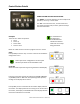
WinDiscovery Installation and Operation Using WinDiscovery Open WinDiscovery from the “Start Menu” or by double-clicking the shortcut icon on the desktop. Once you click [Discover], shown below, all network clocks accessible on the network will announce their presence and the status bar will display the count of devices found. When complete, a list of device families and groups will be displayed in the left pane of the WinDiscovery window.
Click on the plus [+] sign to the left of any family or group to open and view device types that were found. Click on the minus [-] sign to close and not show the device family or group. Click on any device group and it will list the devices in the right pane with all devices of that type found. To configure another device group, click on the device name in the left window and the device names will then appear in the right window, ready to be managed.
Below: This menu appears following a right click on device name. INSIDE THE DROP DOWN MENU WINDOW: PROPERTIES Click the [Properties] button to view the “Properties” window (middle left). This presents a summary of the current Network Configuration and cannot be changed except through the other windows. NETWORK CONFIGURATION The network configuration (middle right) may be viewed in summary by clicking the [Network Configuration] button. Properties Window DEVICE SETTINGS The “Device Settings” window (pg.
When a password is set for a device, each time you click [OK], [Apply] or [Apply and Close] for that device you will be asked for the password. You can select the [Remember this password for the session] button and you will not be prompted for the password, until you restart WinDiscovery. Or you can use the Global Password feature (see below).
Enabling / Disabling Global Password 1. Enable the global password feature by selecting the “Enable Global Password” checkbox. 2. Type the global password 3. Click [OK] Select by clicking To disable the Global Password, de-select the “Enable Global Password” checkbox and click [OK]. SET TIME/DATE Click the [Set Time/Date] button and a window appears reminding the user, “This feature is only to be used to set the UTC time and date if the device is not locked to a reference and is free-wheeling.
Device Settings The device settings window will display network device and can be configured to display time in the format that you prefer, using time zone offsets and DST settings to completely customize it relative to UTC time. The top right section of the Window shows the current firmware version and serial number of the device. 22 When working in these management windows use the [Apply], [Apply and Close] and [OK] buttons to accept changes that you have made.
NTP CLIENT While on the “Input Control” window, click the [NTP Client] button to access settings for the NTP client. ENABLE NTP CLIENT – is enabled by default. However, it may be desirable to disable the NTP client for certain applications, such as those in which the RC 500 will not reside on a network during typical operation. Deselect “Enable NTP client” if desired.
Listen for NTP via broadcasts address The network clock can be configured to listen to NTP broadcasts by selecting the “Listen for NTP via broadcast address “255.255.255.255” checkbox. Select by clicking 24 The Broadcast timeout period is adjustable when this mode is selected. The default configuration is to query the NTP server at 10-minute intervals. The clock drift is +/- 1 minute per year, so you can adjust as need.
Listen for NTP via multicast address(s) The network device can be set up to listen to NTP using multicast addressing by selecting the “Listen for NTP via multicast address(s)” checkbox. Select by clicking 25 When enabled, the multicast class D / group address may be specified as well as the frequency that multicast broadcasts will be issued. This can be changed as desired. The network clock can listen for NTP multicast broadcasts using the full class D/ group address range.
NTP SERVER NAMES – By default the [Use NTP server provided by the DHCP server] box is checked and a primary NTP server address is displayed. If you wish to uncheck the box and provide your own server addresses for both primary and secondary servers, do so here. NTP CLIENT AUTHENTICATION SETTINGS – This window permits the entering of up to 15 MD5 key values to be trusted or allowed.
NETWORK CONFIGURATION The “Network Configuration” window may be viewed in summary by clicking the [Network Configuration] selection. DISPLAY PROPERTIES In the “Display Properties” window (below), you can change the brightness of the display or modify the presentation of the date and time. You can change the display from UTC to local time and you can alternate times with dates and set the rate at which they change.
COMMUNICATIONS CONTROL (TELNET OPTION) Certain advanced features may be configured using the [Communications Control] button. This gives access to the “Telnet Control” window (below). If Telnet is allowed, the port must be defined. The default Telnet port is 23. See your network administrator if you need additional information. CLOCK CONTROL SETTINGS Click the [Clock Control Settings] button to access the RC500 “Clock Assignment” window.
Use the buttons located in the center to move a device from the “Available” to the “Assigned” column. Move all available clock displays by pressing [All >] and [< All] respectably and [>] and [<] to move individual clock displays. When finished, click [Ok] and the assignment will be saved. 29 Clear All Device Assignments / Reset All Control Assignments This feature allows the end user to clear all RC500s and clock displays association.
TIME ZONE/TIME OFFSET SETTINGS Click the [Time Zone/Time Offset] button to open the “Time Zone Configuration” window. This window displays a list of time zones, including descriptions to help with the selection. Select the offset and click [OK] to close the Window. The DST rules will be applied when you click [Apply] or [Apply and Close] from the “Device Settings” window. DAYLIGHT SAVINGS TIME SETTINGS Click [Daylight Saving Time] to open this window.
Time Zone Offsets The RC500 interprets time input as UTC. If the time reference to this unit is not UTC, do not adjust the Time Zone and/or DST offset. A Time Zone offset or bias can be used to adjust the time for display purposes because the default is UTC time. Local or custom time can be set as a positive (+) offset indicating that the unit is earlier than UTC time or negative (-) offset indicating the unit is later than UTC time. See page 30.
The configurations you set are maintained in non-volatile memory allowing your custom settings to be retained during power outages. ADMINISTRATIVE FUNCTIONS (AF) Click the [Administrative Functions] button to open a menu that is rarely accessed. These include: 1.
Soft Restarts A soft restart may periodically be performed by the network device to automatically attempt to rectify a problem it may be experiencing. A soft restart is essentially the same as performing a manual soft reset device as described above. The network device will perform a soft restart under the following conditions: If the device is not receiving an NTP poll response or an NTP broadcast response depending on which mode the device is in.
Reset Configuration through pinhole 1. Located on the rear of the unit is the pinhole to the reset button (i.e. next to the RJ45 Ethernet port). 2. While the unit is powered on, insert a non-metallic reset tool straight through the pinhole and hold the button for proximity 5 seconds or until the display shows dashes. Reset button through pinhole The unit will go through an initialization process and will show the time on the display when reset is complete.
Time adjustments are changes to the internal time reference as compared to the NTP server. 1. While acquisition of NTP server. Initial startup After loss of power After loss of NTP 2. Change to the device configurations.
Telnet Those with Linux and other non-Windows operating will not be able to use WinDiscovery. Configuration via Telnet may not be convenient for devices operating with a factory default configuration since the IP address is not known. Use the WinDiscovery application to establish first-time networking configuration. A terminal-style configuration interface is available via Telnet.
TELNET A login prompt is presented if a password has been configured for the device. The configuration menu will be displayed when the correct password has been provided. The factory default password is: “public”. Type “?” to display the screen at left. (See this and commands like this at the bottom of the Telnet screen at left.) 37 Type “help” to display the abbreviated screen at left. Type the command name corresponding to the desired action (such as “timezone” then press [Enter] or [Return].
TELNET CURRENT CONFIGURATION/ DEFAULT SETTINGS Current configurations default settings are displayed. Depressing the [Enter]/ [Return] key with no number or letter will retain the current setting. Depressing the [Enter] or [Return] key with no number or letter will retain the current setting. brightness ─ Default: 4 Show or change the Brightness level of the LED display and button illumination. debug ─ Default: Disabled Show or change the debug output settings.
reboot Reboot the device reflossdashes Show or change displaying dashes on reference loss settodefault Reset the device to factory default or restart Speaker - Default: On Show or change the speaker output setting status Show status information by querying the device parameters. This includes information regarding the reference to UTC, local time, displayed time, whether it is synchronized, etc. telnet - Default: 23 Show or change the Telnet port and/or turn off Telnet access.
Specifications Communications I/O Connectors RJ12 .................................................................. RS485 communication with TCDS Digital Time display RJ45 .................................................................. Ethernet communication with NTDS Digital Time display Power AC Voltage ............................................................ 100-240 VAC Frequency ......................................................... 50/60 Hz Consumption .......................................
Problems - Troubleshooting Unable to communicate to slave display / clock Possible reasons/solutions: 1. Verify the correct RJ12 (6P6C) modular cable is being used (i.e. 6 conductor). 2. Verify all connections are secure between the RC500 and slave display/clock. 3. Check to make sure power is applied to all devices. 4. Check the cables for hard bends, kinks, or cuts. 5. Verify that the correct adapters and splitters are being used (i.e. 6P6C).
4. If the computer is separated from the device by a router (on a remote network) or a firewall it is likely that the router/firewall is blocking communications with the device. Run WinDiscovery from a computer within the remote network, or ask a network system administrator to configure the router/firewall in question to pass through (both directions) UDP broadcasts on port 6163.
is saved and returned as an error to WinDiscovery. This error status is available to the user via the Status window on WinDiscovery. If the configuration of the network device is changed while a 169.254.xxx.xxx is being use, then the current 169.254.xxx.xxx address will become the permanent static address and the original conflicting static address is lost.
Care and Cleaning Adherence to regular and proper cleaning procedures is recommended to preserve appearance. Scratched or otherwise damaged lens caused by misuse, mishandling and improper storage or improper cleaning is not covered under the limited warranty. Job Site Precautions It is recommended the unit be removed and stored in a protective area during painting and/or construction.
Service Information We sincerely hope that you never experience a problem with any Masterclock product. If you do need service, contact Masterclock’s Technical Support team. A trained specialist will help you to quickly determine the source of the problem. Many problems are easily resolved with a single phone call or email. If it is necessary to return a unit to us, an RMA (Return Material Authorization) number will be given to you. Visit our website to download a current RMA request form. http://www.
Limited Warranty This Masterclock product warranty extends to the original purchaser. Masterclock warrants this RC 500 against defects in materials and workmanship for a period of five years from the date of sale. If Masterclock receives notice of such defects during the warranty period, Masterclock will, at its option, either repair or replace products that prove to be defective.
Compliance 47 Masterclock RC 500 User Manual – v2014.01.
Compliance CE Marking Electromagnetic Compatibility 2004/108/EC Tested and Conforms to the following EMC standards : EN 61000-4-2:1995 +A1:1998 +A2:2001 (Electrostatic Discharge) EN 61000-4-3:2006 +A1:2008 (RF Immunity) EN 61000-4-4:2004 (Fast Transient Common Mode) EN 61000-4-5: 2006 (Surge) EN 61000-4-6: 2007 (RF Injection Common Mode) EN 61000-4-8: 1993 +A1:2001 (Power Frequency Magnetic Field) EN 61000-4-11: 2004 (Voltage Dips) EN 61000-6-3:2001 (EMC Emissions Generic Commercial) EN 55022:2006 +A1:2007
This device complies with Part 15 of the FCC Rules and found to comply with the limits for a Class B digital device. These limits are designed to provide reasonable protection against harmful interference in a commercial/residential installation.
Contact Us Masterclock, Inc. 2484 West Clay Street St. Charles, MO 63301 USA website www.masterclock.com USA and Canada 1-800-940-2248 1-636-724-3666 1-636-724-3776 (fax) International 1-636-724-3666 1-636-724-3776 (fax) 50 Sales sales@masterclock.com Technical Support support@masterclock.com Copyrights Copyright © 2011 Masterclock, Inc. All rights reserved.