
Specifications

AD1974 Data Sheet
Rev. D | Page 14 of 24
LEFT RIGHT
MSB MSB
MSB MSB
MSB
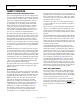
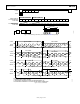
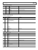
ADCL1 ADCR1 ADCL2 ADCR2 AUXL1 AUXR1 AUXL2 AUXR2 UNUSED UNUSED UNUSED UNUSEDUNUSED UNUSED UNUSED UNUSED
FOUR-ON-CHIP
ADC CHANNELS AUXILIARY ADC CHANNELS UNUSED SLOTS
32 BITS
06614-052
AUXLRCLK
(AUX PORT)
AUXBCLK
(AUX PORT)
AUXDATA1
(AUX1_IN)
AUXDATA2
(AUX2_IN)
ALRCLK
ABCLK
ASDATA1
(TDM_OUT)
Figure 8. 16-Channel AUX ADC Mode
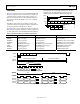
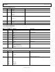
DAISY-CHAIN MODE
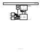
The AD1974 also allows a daisy-chain configuration to
expand the system to 8 ADCs and 16 ADCs (see Figure 9 and
Figure 10). There are two configurations for the ADC port to
work in daisy-chain mode. The first one is with an ABCLK at
256 f
S
shown in Figure 9. The second configuration is with an
ABCLK at 512 f
S
shown in Figure 10. Note that in the 512 f
S
ABCLK mode, the ADC channels occupy the first eight slots,
the second eight slots are empty. The TDM_IN of the first
AD1974 must be grounded in all modes of operation. The
second AD1974 is the device attached to the DSP TDM port.
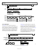
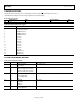
The I/O pins of the serial ports are defined according to the
serial mode selected. See Table 13 for a detailed description
of the function of each pin. See Figure 14 for a typical AD1974
configuration with two external stereo ADCs.
Figure 11 through Figure 13 show the serial mode formats.
For maximum flexibility, the polarity of LRCLK and BCLK
are programmable. All of the clocks are shown with their
normal polarity. The default mode is I
2
S.
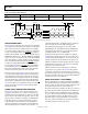
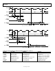
ALRCLK
ABCLK
ASDATA2 (TDM_IN
OF THE SECOND AD1974
IN THE CHAIN)
ADCL1 ADCR1 ADCL2 ADCR2
FOUR ADC CHANNELS OF THE FIRST IC IN THE CHAINFOUR ADC CHANNELS OF THE SECOND IC IN THE CHAIN
ASDATA1 (TDM_OUT
OF THE SECOND AD1974
IN THE CHAIN)
ADCL1 ADCR1 ADCL2 ADCR2 ADCL1 ADCR1 ADCL2 ADCR2
32 BITS
MSB
DSP
SECOND
AD1974
FIRST
AD1974
06614-056
Figure 9. ADC TDM Daisy-Chain Mode (256 f
S
ABCLK, Two AD1974 Daisy Chains)