
Technical data


INSTALLATIONINSTRUCTIONS
Assemblyandelectricalconnectionsmustbecarriedoutbyspecializedpersonnel.
•ElectricConnection
TheappliancehasbeenmanufacturedasaclassI,thereforeearthcableisnecessary.
Theconnectiontothemainsiscarriedoutasfollows:
Ifnotprovided,connectaplugfortheelectricalloadindicatedonthedescriptionlabel.
Whereaplugisprovided,thecookerhoodmustbeinstalledinorderthattheplugiseasily
accessible.
Anomnipolarswitchwithaminimumapertureof3mmbetweencontacts,inlinewiththe
electricalloadandlocalstandards,mustbeplacedbetweentheapplianceandthenetwork
inthecaseofdirectconnectiontotheelectricalnetwork.
• Theminimumdistancebetweenthesupportsurfacesofthecookingpotsonthecooker
topandthelowestpartofthecookerhoodmustbeatleast65cm.Ifaconnectiontube
composedoftwopartsisused,theupperpartmustbeplacedoutsidethelowerpart.
Donotconnectthecookerhoodexhausttothesameconductorusedtocirculatehotairor
forevacuatingfumesfromotherappliancesgeneratedbyotherthananelectricalsource.
Beforeproceedingwiththeassemblyoperations,removetheanti-greasefilter(s)(Fig.5)so
thattheunitiseasiertohandle.
Inthecaseofassemblyoftheapplianceinthesuctionversionpreparetheholefor
evacuationoftheair.
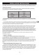
Drilltheholes A respectingthedistancesindicated(Fig.2).
Fixtheappliancetothewallandalignitinhorizontalpositiontothewallunits.Whenthe
appliancehasbeenadjusted,definitelyfixthehoodusingthescrews A.
Forthevariousinstallationsusescrewsandscrewanchorssuitedtothetypeofwall(e.g.
reinforcedconcrete,plasterboard,etc.).Ifthescrewsandscrewanchorsareprovidedwith
theproductcheckthattheyaresuitableforthetypeofwallonwhichthehoodistobe
fixed.
Arrangetheelectricalpowersupplywithinthedimensionsofthedecorativeflue.Ifyour
applianceistobeinstalledintheductingversion,preparetheairexhaustopening. Adjust
thewidthofthesupportbracketoftheupperflue(Fig.3). Thenfixittotheceilingusingthe
screws A (Fig.2)insuchawaythatitisinlinewithyourhoodandrespectingthedistance
fromtheceilingindicatedinFig.2.ConnecttheflangeCtotheairexhaustholeusinga
connectionpipe(Fig.4).
?
?
FIXINGTOTHEWALL
FIXINGTHEDECORATIVETELESCOPICFLUE
IEC227
L=live
N=neutral
E=earth
Brown
Blue
Green/Yellow
19
GB