RECOVERY/RECYCLE/RECHARGE Operating Instructions WARNING!! Do not stop the recovery process. Permanent damage will occur that could void the warranty.
CONTENTS INTRODUCTION 4 SAFETY SUMMARY 4 SAFETY INFORMATION 4 ELECTRICAL SHOCK HAZARDS 4 MOTION HAZARDS 5 FUME HAZARDS 5 HEAT/FREEZING HAZARDS 5 EXPLOSION/FLAME HAZARDS 5 ADDITIONAL SAFETY INFORMATION 5 CERTIFICATION 6 ABOUT THIS MANUAL 6 ABOUT YOUR AIR CONDITIONING RECOVERY/RECYCLE SERVICE CENTER 6 WARRANTY 6 GENERAL INFORMATION 6 PRINCIPLES OF OPERATION 7 SETUP 7 THE MACHINE 8 BASIC COMPONENTS 8 CONTROLS AND CONTROL SYSTEM 9 FUNCTION SELECTOR KEYBOARD 9 ALARMS 9 P
PRESSURE 21 TEMPERATURE 21 DATA 21 PASSWORD PROTECTION 22 CUSTOMIZING THE DBA (DATABASE ADVANCED) 23 DATA ENTRY 23 USE 23 DELETION 23 DATABASE UPGRADE 24 CONVERSION CHART 24 3
INTRODUCTION This machine is ETL Laboratories approved, in compliance with SAE J2788. We are dedicated to solving the issues surrounding the safe containment and proper management of refrigerants. Your new machine incorporates the latest technology and state of the art features to aid you in servicing R134a air conditioning and refrigeration systems. NOTICE: The SAE J2788 standard has, by design made recycling machines more complex than previous models that some End Users might be familiar with.
MOTION HAZARDS • Engine parts that are in motion and unexpected movement of a vehicle can injure or kill. When working near moving engine parts, wear snug fit clothing and keep hands and fingers away from moving parts. Keep hoses and tools clear of moving parts. Always stay clear of moving engine parts. Hoses and tools can be thrown through the air if not kept clear of moving engine parts. • The unexpected movement of a vehicle can injure or kill.
mixtures of air and R134a have been shown to be combustible at elevated pressures. These mixtures, if ignited, may cause injury or property damage. Additional health and safety information may be obtained from refrigerant manufacturers. ATTENTION: Technicians using this equipment must be certified under EPA Section 609 (Environmental Protection Agency). WARNING: There is the possibility of refrigerant contamination in the refrigerant container or the mobile A/C system being serviced or refrigerant container.
the Manufacturer are such that during work, the average noise level of the machine is less than 70 dB (A). NOTE: The machine is intended for indoor use only. ������ ������ PRINCIPLES OF OPERATION In a single series of operations, the machine permits recovering and recycling refrigerant with no risk of release into the environment, and also permits purging the A/C system of humidity and deposits contained in the oil.
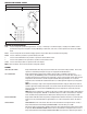
THE MACHINE BASIC COMPONENTS (Refer to Figures 5, 6, 7 and 8.) A) Control Console B) Service Valves C) High & Low Service Ports G) Vacuum Pump H) Wheels I) Main Switch M) Used Oil Bottle N) Drier Filters O) Tank D) New Oil Bottle E) Sight Glass F) Serial Port J) Socket for Electrical K) Fuse Holder Supply Plug P) Tank Heater L) Electronic Scale � � � � � � FIG. 5 FIG. 6 � � � � � � � � � FIG. 7 8 FIG.
CONTROLS AND CONTROL SYSTEM Refer to Figure 9. A1) High pressure gauge A2) Low pressure gauge A3) Keyboard A4) LCD: 4 lines, 20 characters �� �� �� �� FIG. 9 FUNCTION SELECTOR KEYBOARD STOP: Press to interrupt the operation being performed -- recovery - oil discharge - vacuum/oil charging - charging. Press START to resume operation from the point of interruption. Pressing STOP during an alarm state, error state, or end-of-operation state silences the audible alarm.
of the screen. To deactivate the alarm, the filters will need to be replaced (see page 18, Replacing the dryer filters.) NOTE: It is good practice to change the Vacuum pump oil when the filters are being changed. (see page 17 & 18, Vacuum Pump) LOW REFRIGERANT ALARM: Beeper and the LCD advise when the charging quantity set exceeds the amount of refrigerant available. The minimum quantity of refrigerant is 4.50 lbs. If the gas available minus the charge quantity equals less than 4.
1. Set the quantity of refrigerant required for the A/C system to be charged. Following are examples for each set of units. Lb, the display will have 4 digits, two digits then a decimal point and then two digits. The cursor moves from the left to the right. If the desired charge is 1.75 lbs, then you will enter 0 1 7 5. Oz, the display will have 3 digits. The cursor moves from the right to the left. If the desired charge is 36 oz’s, then you will enter 0 3 6. Gr, the display will have 5 digits.
Upon completion of discharge, the machine will check for the presence of air in the tank, and if it’s necessary, purge the non condensable gases. The alarm will sound continuously and the display will show: AIR PURGE Recovery Tp: xx ref x:xx psi lb T:xx ˚F The Recovery/Recycle machine will automatically purge non-condensable gases (NCGS) if excess NCGS are detected at the end of recovery. Allow the unit to complete this procedure, eliminating the chance of NCGS being charged to the AC system.
ALLOW HIGH PRESSURE CLOSE TO AND EQUALIZE ALL RESET: LOW WHEN VALVES COMPLETE ASSISTED PROCEDURE WARNING: DO NOT STOP THE RECOVERY PROCESS. Stopping the recovery process will definitely cause damage to the Compressor and perhaps other components. It will also cause the machine to fill up with unprocessed liquid refrigerant which will disable the machine from further use. Damage due to STOPPING THE RECOVERY PROCESS could void the warranty.
oil valve when reaching the desired oil level. ATTENTION: Since the oil in the container will decrease in level, the quantity must be calculated by difference. Upon completion of the oil injection phase, you may go on to refrigerant fluid charging. NOTE: Using PAG oil or tracer in hybrid vehicles may damage the compressor. Use only suitable oil with a separate oil injection device. ��������� ������������������� FIG.
Where “w:yz” refers to the quantity for the vehicle selected. The machine will be ready to enter the correct quantity of refrigerant. Confirm by pressing the ENTER key. Open the high and low service valves on the machine and press the START key (in the case of an A/C system with a single high or low pressure coupling, open only the relative valve on the machine). NOTE: Charging may not run to completion due to pressure balance between the internal tank and the A/C system.
Select LAST RECOVERED QTY: LAST RECOVERED XX.XX STOP: QTY LB MAIN MENU This valve gets updated after each complete recovery phase. ROUTINE MAINTENANCE FILLING THE MACHINE TANK This operation must be performed whenever the available refrigerant fluid in the tank is less than 9 lbs (4.8 kg) and must be performed when the “Empty Tank” alarm is displayed. Recommended capacity is between 10 and 15 lbs. Obtain a tank of R134a. Connect the tank adapter fitting (69788-332) to the R134a tank.
The machine will now fill the machine tank with the preset quantity ±1.1lb (≈500g). When the quantity minus 1.1lb (≈500g) is reached, the machine will stop and display: TANK CHARGING Close the tank and external PRESS START Close the tank valve and press START. The machine will stop automatically after having recovered the residual refrigerant from the hoses. Close the high pressure valve. Disconnect the external tank.
1) Disconnect the machine from the electrical supply. 2) Remove the rear cover (6 screws.) 3) Unscrew the oil fill/muffler plug (Fig 11.2.) 4) Unscrew the drain plug (Fig. 11.3.) 5) Allow all the oil to run out into a disposal container (drain clearance is less than 3.95 inches.) 6) Close the drain plug (Fig. 11-3.) 7) Pour in new oil through the fill hole until the level rises to the midpoint on the indicators (Fig. 11-4.) 8) Replace the oil fill/muffler plug (Fig. 11-2.
� supplied.) Lift the quick-connect coupling near the top of the container and remove the container complete with cap. Unscrew the cap and fill the container � with the correct quantity of oil of suitable type and grade. Screw the cap back on and, lifting the quick-connect coupling as above, replace the container in its holder. � EMPTYING THE USED OIL CONTAINER � operation must be performed whenever the oil level exceeds 6.7 oz (200 cc.) This Procedure: Remove the container from its holder.
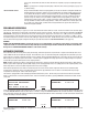
DATA SERVICES PREVIOUS MENU Select CONFIGURATION: MEASURE UNITS PREVIOUS MENU ENGLISH <- Select LANGUAGE: ITALIANO FRANCAIS ESPANOL NOTE: The current language is indicated by the symbol “<-“. Use the ARROW keys to scroll the available languages. Confirm a language by pressing ENTER. The machine will reset and a few seconds later the MAIN MENU will appear in the chosen language. UNITS OF MEASUREMENT Switch the machine on.
WEIGHT Select WEIGHT: WEIGHT (lb) PRESSURE psi TEMPERATURE ˚F EXIT Press ENTER to change from lb, oz, gr, Kg or lb:oz WEIGHT (lb) PRESSURE psi TEMPERATURE ˚F EXIT Select another parameter or EXIT to go to the previous screen. PRESSURE Select PRESSURE: WEIGHT (lb) PRESSURE psi TEMPERATURE ˚F EXIT Press ENTER to change from bar to psi or from psi to bar. WEIGHT (lb) PRESSURE psi TEMPERATURE ˚F EXIT Select another parameter or EXIT to go to the previous screen.
Select NEXT MENU: LAST RECOVERED TANK CHARGING AIR QTY PURGE Select DATA AND CONFIGURAT.: CONFIGURATION SERVICES PREVIOUS MENU Select DATA. The following screen will be displayed: Ref avail XX.XX temper XX.X°F Tank Press XX psi xx psi lb Tank ACp NOTE: TP: xx psi will be flashing - Ref avail.: quantity of refrigerant available in the storage tank. - Tank temp.: temperature of the refrigerant storage tank. - Tp: pressure of refrigerant tank.
Select PASSWORD: .... Put in your own 4 digit password and press enter. CUSTOMIZING THE DBA (DATABASE ADVANCED) Select ASSISTED PROCEDURE. Scroll down with the (↓) DOWN arrow key until the vehicle brands in the DBA appear: AUDI BMW CHRYSLER/JEEP Press the (↑) UP arrow key: TOYOTA VOLKSWAGEN VOLVO Select the USER DEFINED option: HIJK MNOP ???? ???? DATA ENTRY To enter customized data, press START. The following screen will be displayed: MODEL NAME: .....
database data must nevertheless be considered purely indicative; the manufacturer declines any and all responsibility for incorrect data. DATABASE UPGRADE Database upgrades are available. Call 973-252-9119 and ask for details. CONVERSION CHART Ounces (oz) to pounds (lbs): divide by 16 Pounds (lbs) to ounces (oz): multiply by 16 Ounces (oz) to grams (g): multiply by 28.4 Grams (g) to ounces (oz): divide by 28.4 Pounds (lbs) to kilograms (kg): divide by 2.