72968-R11.
MasterCool® MCP Series Evaporative Window Cooler Installation and Operating Manual Congratulations on your purchase of the MasterCool® MCP Series plastic evaporative cooler. This unit is manufactured with the intent of offering you years of reliable, efficient cooling. NOTE: READ THESE INSTRUCTIONS BEFORE INSTALLING THE COOLER. Follow the installation instructions in this manual carefully. Varying from them may create safety concerns and will void the warranty. Safety Instructions 1.
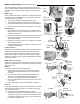
BEFORE INSTALLING WARNING: Do not connect electrical power to the unit until the installation is completed. Parts The MasterCool MCP Series cooler can be installed in a sash-style or a slider-style window. Alternatively, this unit is approved for in-wall installations. REQUIRED CLEARANCES/ SPECIFICATIONS: In all installations, the following clearances are required: • • • Width: 22” Height: 22” PLUS: 4” additional space required above exterior of cabinet for maintenance. Weight: 93 lbs operating weight.
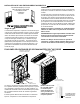
WATER CONNECTIONS (see illustrations at right) The cooler operates by water being pumped from the bottom pan through a water distribution system to saturate cellulose media pads. The water lines are snapped into plastic keepers along the inside of the unit. 1. 3. OVERFLOW DRAIN Water Pump 1. 2. The pump and water lines are shipped disconnected. The overflow drain (ITEM G) is attached to the drain line and should be pushed down to be flush with the end of the drain tube. 3.
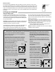
Remote Control The remote control supplied with this cooler allows you to turn the unit on or off, control fan speed and initiate the pump. The buttons operate in the same manner as those on the front control panel. The remote control’s range is approximately 20 feet within sight of the cooler. Two AA alkaline batteries are included. Remove the guard between the batteries to activate the remote. It is now ready for use. A wall mountable holder is also supplied with the remote.
Annual Maintenance (Con’t) WATER DISTRIBUTOR Water Distributor 1. Inspect the water distribution section to ensure all orifices are clear. 2. Verify the hose connections are in good order and no kinks or tears are present. Water Drain Overflow 3. On the bottom of the cooler, unscrew the plastic nut holding the overflow drain in place. Push the drain up into the cooler base to allow rapid draining. Check the condition of the gasket at the bottom of the fixture.
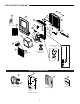
COOLER PARTS DIAGRAM 2 21 4 12 1 5 ON PUMP FAN CHAMPION / ESSICK AIR (2 ea.) 20 6 13 3 7 14 16 11 8 15 19 MCP SERIES COOLER (1 pump) 17 18 10 (OPTIONAL OWNER INSTALLED PURGE PUMP) (4 ea.
MASTERCOOL MCP SERIES COOLER ONE YEAR LIMITED WARRANTY SALES RECEIPT REQUIRED AS PROOF OF PURCHASE FOR ALL WARRANTY CLAIMS.
NOTA ACERCA DE LOS ENFRIADORES EVAPORATIVO Ventilación: Para enfridaor trabajar mejor, tiene que A diferencia de los acondicionadores de aire, los enfriadores haber una vnetana o puerta abierta evaporativo necesitan un sistema de ventilación abierto y no en cada habitacion donde cerrado. el enfriamiento es deseado. Se requieren tanto una fuente de aire fresco como una apertura de escape para generar una correcta circulación de aire.
PROCEDIMIENTOS DE INSTALACIÓN (consulte las ilustraciones de la derecha) Carcasa del ventilador segura 1. 2. En la sección frontal, extienda la carcasa del ventilador completamente desde el armazón. Utilice 12 tornillos (ARTÍCULO C) para asegurar el módulo del ventilador en el lugar. MÍNIMO DE 4" TENGA EN CUENTA EL ANCHO DEL BORDE DEL MÓDULO DEL VENTILADOR Instalación en la ventana NOTA: Recomendamos dos personas para la instalación. 1.
CIERRE DEL ENFRIADOR Después de completar las conexiones de agua, cierre la unidad al reposicionar el enfriador de vuelta en el enfriador instalado y vuelva a colocar los cuatro tornillos que aseguran la parte frontal y posterior del enfriador juntas. ARTÍCULO Pasos finales Antes de encender la unidad, asegúrese de que está conectada, que el suministro de agua a la bomba está encendido y que se cuenta con una correcta ventilación, tal como se indica en la página 3 de este manual.
ACCESORIOS OPCIONALES (CONTINUACIÓN) Uso del termostato complementario opcional La serie MCP también se puede controlar mediante un termostato programable complementario, como el WIN 100 de la marca LUX. Estos termostatos pueden adquirirse a nivel local y permiten un control preciso del tiempo y la temperatura a través de un termostato electrónico que se conecta a un tomacorriente de 110 V.
DIAGRAMA DE PIEZAS DEL ENFRIADOR 2 AR PIS 4 12 NO 21 1 5 ON PUMP FAN CHAMPION / ESSICK AIR (4 c/u) 20 6 13 3 7 11 14 16 8 15 19 ENFRIADOR SERIE MCP (1 bomba) 17 18 10 BOMBA DE PURGA OPCIONAL (INSTALADA POR EL USUARIO) (4 c/u) 9 ACCESORIOS OPCIONALES 23 22 24 25 CUBIERTA INTERIOR KIT DE BOMBA DE PURGA CUBIERTA EXTERIOR El kit incluye un juego completo de medios, clavijas y retenedores KIT DE REEMPLAZO DE ALMOHADILLA 24
Tabla de solución de problemas PROBLEMA No arranca la unidad CAUSA PROBABLE SOLUCIÓN a. No hay energía a. Compruebe que la unidad esté conectada y que el tomacorriente esté operativo b. Restablezca el disyuntor c. Reemplace el fusible en casa d. Llame a la línea telefónica de ayuda de Champion b. Disyuntor activado c. Fusible quemado (en casa) d. Falla eléctrica Enfriamiento deficiente a. Distribución de agua inadecuada (almohadillas no saturadas) b.
CHAMPION COOLER 5800 MURRAY ST. LITTLE ROCK, AR 72209 www.championcooler.