
Use and Care Guide


6
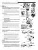
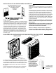
PLASTIC OR
COPPER LINE
TO COOLER
SHUT OFF VALVE
SILL-COCK
STD. HOSE CONNECTION
The cooler operates by water being pumped from the bottom pan
through a water distribution system to saturate cellulose media pads.
The
water lines are snapped into plastic keepers along the inside of
the unit.
Water Pump
A self-contained water pump continuously circulates water through
black plastic lines to a distribution tray in the top of the cooler that
percolates water over the media.
1. The pump and water lines are shipped disconnected.
2. The overfl ow drain (ITEM G) is attached to the drain line and
should be pushed down to be fl ush with the end of the drain tube.
3. Push the other portion of water line onto the intake port on the pump
.
Overfl ow Drain
4. Remove the nut on the end of the drain and insert the fi tting
through the hole in the cooler bottom. Then tighten the nut on
the bottom of the cooler.
5. Make sure the rubber washer (installed inside reservoir) does
not twist while tightening, which could cause it to leak. DO
NOT OVER TIGHTEN.
6. If leakage occurs after reservoir is full, re-tighten the overfl ow
fi tting until leaking stops.
7. A standard water hose can be attached to exterior portion of
the overfl ow drain fi tting to
Float Connection
The fl oat has been installed in bottom of the cooler with ferrule and
compression nut zipped tied to the fl oat. Cut these free for use
(as described below) with water line installation. The fl oat level is
factory set to maintain 2 inches of water in the reservoir. After in-
stallation is complete the fl oat might need readjustment by slightly
bending the fl oat arm.
Water Source Connection
Steady water supply is required for operation of the cooler. If taking
water from an external faucet, there are two options for attaching
water to the cooler.
Option 1:
If using a standard water hose to supply water:
1. Install the fl oat and red gasket on the inside of the cooler,
securing them with the threaded jam nut on the outside of
the cooler.
2. On the exterior, screw the small nut inside the water hose
connector onto the threaded fl oat valve port. Can use a
14mm wrench to tighten. DO NOT OVERTIGHTEN.
3. Screw a standard water hose into the connector. Verify wash-
er is in place.
4. Leave water spigot turned off until installation is complete.
Option 2:
A more permanent supply of water can be installed from an outside
water faucet by installing a sill-cock and 1/4" water line to supply
continuously to the cooler.
1. Install a sill-cock (locally available) onto the faucet.
2. Determine length of water line needed and install one end of
1/4" plastic or copper line on sill-cock and use the ferrule and
nut (zip-tied to the fl oat for packing) to connect the water line
to the fl oat valve attach point.
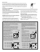
WATER CONNECTIONS
FLOAT VALVE
GASKET
JAM
NUT
WATER HOSE
CONNECTOR
WASHER
FERRULE
TO
STANDARD
WATER
HOSE
COMPRESSION NUT
TO 1/4"
WATER LINE
FLOAT VALVE
WATER LINE
ATTACH POINT
VIEW FROM
BOTTOM
VIEW FROM TOP
(see illustrations at right)
INTERIOR
EXTERIOR
DRAIN LINE FLUSH
WITH OVERFLOW
DRAIN
OVER-
FLOW
DRAIN
OPTION 1
INTERIOR EXTERIOR
OPTION 2
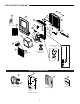
WASHER
COOLER
BOTTOM
NUT
OVERFLOW
DRAIN
1.
2.
3.
4.
6.
5.
LOCATION
OF DRAIN
TO WATER
DISTRIBUTION
WATER PUMP
OVERBOARD
DRAIN