
Use and Care Manual


2
110522-3
COOLER ASSEMBLY
NOTE: Installation kit and manual are inside the unit.
1. Unpack unit from carton. Please recycle and discard of packing material responsibly.
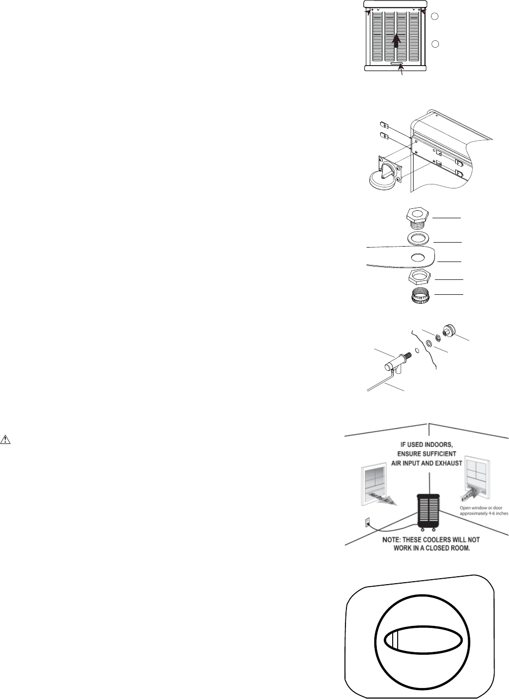
2. Two screws secure each louver panel. Locate and remove the screws about 1-1/2 inches
below the plastic work top. Replace these screws when re-installing panel.
3. Access the interior of the unit by using the handhold at the bottom of the louvered side to
lift up and out of the cabinet. Locate and remove the plastic bag of parts and manual.
CASTER INSTALLATION
NOTE: The installation kit includes (2) swivel casters with brake, (2) swivel casters
without brake, (16) tinnerman nuts and (16) 1/4-20 x 1/2 screws.
1. Place the unit on its side. Place the tinnerman nuts on the caster bracket on the bottom pan.
2. Attach the casters to the brackets with the screws provided. See illustration at right.
WATER CONNECTION
In addition to containing a large reservoir, this unit can have constant water supply via a com-
mon water hose or designated water line.
• Install drain assembly. Place the nipple through the hole in the pan, with the rubber
washer between the pan and the head of the drain nipple. Thread nut onto nipple and
draw up tight against bottom of pan. Thread the drain cap to the nipple and tighten water tigh
t.
• Install fl oat valve. Refer to fi gure at right. Install the valve in the provided hole in the
corner post using the provided washer and nut. Install the included garden hose adapter
to the fl oat as shown if attaching a garden hose to the unit. A 1/4 inch water line may
also be used to supply a continuous amount of water to the unit.
• Fill pan with water. You may fi ll the pan manually for up to 3 hours of cooling. For auto-
matic fi lling you may attach a garden hose to the garden hose adapter or a 1/4 inch water
line to the fl oat valve.
Note: Do Not Overfi ll. Fill water to a maximum height of 2 1/2 inches (approximately 1
inch from the top of the bottom pan).
If using a garden hose or water line, the fl oat will need
to be adjusted
to maintain this water level. This can be accomplished by bending the fl oat
rod.
OPERATION
LOCATION
• When setting up the MasterCool MMBT unit in an outdoor location, take into consider-
ation the following cautions:
HAND HOLD
PUSH PANEL UP,
ANGLE BOTTOM
OUT, AND
REMOVE PANEL.
1
REMOVE 2 SCREWS AT
TOP OUTSIDE OF LOUVER
PANEL
2
NIPPLE
RUBBER
WASHER
BOTTOM
OF COOLER
NUT
DRAIN CAP
WATER
HOSE
CONNECTION
NUT
WASHER
FLOAT
FLOAT ROD
CONTROLS
This unit can be used as a fan only or as an evaporative cooler. The six-position switch
allows for two speeds in fan mode (VENT), two speeds for COOL mode, a separate
PUMP position to pre-wet the pads, and an OFF position.
COOLING MODE:
1. If cooling pads are dry, place the knob in the PUMP ONLY position about 3 minutes to
allow the cooling pads to wet before turning on fan.
2. Turn the switch to either HIGH COOL or LOW COOL to start the fan in cooling mode.
NOTES: The pump will automatically turn on when the HIGH or LOW COOL position is
selected.
Use the LOW COOL setting whenever possible. This lower speed causes
the air to stay longer in the wet pads and therefore increases the cooling
effi ciency.
FAN ONLY MODE:
1. The HIGH VENT or LOW VENT positions will start the fan only, without water.
PUMP
ONLY
POWER
OFF
LOW
HIGH
COOL
LOW
COOL
VENT
HIGH
VENT
CAUTIONS: Ensure power cord is secured and does not pose a tripping hazard.
Similarly, if using a water hose for constant water supply, lock unit casters, and
secure hose to reduce tripping hazard.
• If the unit is used in an enclosed area, ensure suffi cient outside air intake and
exhaust by opening windows or doors. Without a good source of outside air and an
outlet to exhaust the air, humidity will build up in the enclosed space and the unit
will not cool adequately.