TABLE SAW WITH SLIDING TABLE 055-6742-8 User Manual Toll-free helpline 1-800-689-9928
PAGE SECTION I. Specifications............................................................................................ II. General safety guidelines ........................................................................ III. Electrical information .............................................................................. IV. Know your table saw............................................................................... V. Assembly and adjustments ...............................................
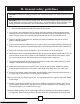
II. General safety guidelines WARNING: Read all the safety guidelines and instructions before you use this electric power tool! WARNING! When using electrical power tools, the following essential safety measures have to be observed to prevent electric shocks, injury and fire hazards. Failure to adhere to the safety guidelines and instructions can cause electric shock, fire and/or severe injuries. 1. 1. Store all safety guidelines and instructions for future use. 2.
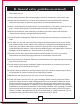
II. General safety guidelines(continued) hair, wear a hair net. 13.Wear safety equipment. Wear safety goggles. If the work creates dust, wear a dust mask. 14.Attach the dust extraction unit. If there are connections for dust extraction and collection equipment, then make sure that the equipment is correctly attached and used. 15.Never use the cable for purposes which it is not intended for. Do not use the cable to pull the plug out of the power socket. Protect the cable form heat, oil and sharp edges. 16.
II. General safety guidelines(continued) 25.WARNING!The use of other insertion tools and accessories can present a danger of injury to you. 26.Let a specialist electrician repair your electric power tool. This electric power tool corresponds to the applicable safety conditions. Repairs are only allowed to be carried out by a specialist electrician, using original replacement parts; otherwise accidents may occur. Additional safety guidelines for circular table saws 27.
II. General safety guidelines(continued) 38.Never reach into the openings of the device! Never insert objects into the openings of the device (e.g. the saw blade casing, dust extraction adaptor). Danger of cuts! 39.Never remove the cutting piece if the machine is still switched on or running! Danger of cutting yourself! 40.Cut workpieces may have sharp edges, ridges or wooden splinters! Danger of cutting injuries! 41.Always switch the machine off and remove the power plug when your leave the machine. 42.
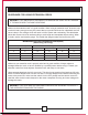
GUIDELINES FOR USING EXTENSION CORDS WARNING: THIS TABLE SAW IS INTENDED FOR INDOOR USE ONLY. DO NOT EXPOSE IT TO RAIN OR USE IT IN DAMP LOCATIONS. Make sure the extension cord is in good condition. When using an extension cord, be sure to use one that is heavy enough to carry the current that your product will draw. An undersized cord will cause a drop in line voltage, which will result in loss of power and overheating.
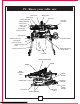
IV.
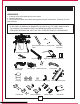
UNPACKING 1. Carefully remove the table saw from the carton. 2. Separate the parts. 3. Lay out all of the parts, and check them against the parts listed below. Examine all of the parts carefully. WARNING: • IF ANY PART IS MISSING OR DAMAGED, DO NOT PLUG THE TABLE SAW IN UNTIL THE MISSING OR DAMAGED PART HAS BEEN REPAIRED OR REPLACED. • FOR MORE INFORMATION, CALL THE TOLL-FREE HELPLINE AT 1-800-689-9928.
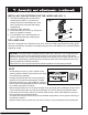
INSTALLING THE BATTERIES FOR THE LASER LINE (FIG. 1) 1. Uninstall the blade guard component by loosening the handle (1). Remove the locking screw(2) on the battery box cover with a screwdriver, and open the battery compartment. 2. Install two “AAA” batteries. 3. Install the battery box cover by closing the screw (2), tighten it securely. 4. Turn the switch (3) to the ON position in order to activate the laser cutting guide. Fig.
CAUTION LASER RADIATION. Do not stare into the beam or view it directly using optical instruments. Maximum output: <5 mW Wavelength: 630-665 nm Protection Class: IIIA Keep Work Areas Clean Accumulated sawdust and wood chips can pose a safety hazard. each cutting operation. WARNING: KEEP THE WORK AREA CLEAN, UNCLUTTERED, AND WELL-LIT. DO NOT WORK ON A FLOOR SURFACE THAT IS SLIPPERY FROM ACCUMULATED SAWDUST, DEBRIS OR WAX. ASSEMBLING THE BLADE RAISING/ TILTING CONTROL HANDLE (FIG. 2) RIP FENCE (FIG.
V. Assembly and adjustments(continued) INSTALLING THE BLADE TO THE ARBOR (FIG. 4, 5, 6) Fig. 4 1. Remove the table insert(1)by inserting the finger into the hole (2&3) (see Fig.4). 2. Raise the saw blade arbor (4) to its maximum height by turning the blade raising control handle counter-clockwise. Remove the arbor nut (5) and the outer flange (6) from the saw arbor. 3. Place the saw blade onto the arbor, with the teeth of the blade pointing DOWN toward the front of the saw. 4.
V. Assembly and adjustments(continued) ASSEMBLING THE BLADE GUARD (Fig. 7, 8 & 9) Fig. 7 VERIFY THAT THE SAW IS DISCONNECTED FROM THE OUTLET BEFORE INSTALLING THE BLADE GUARD AND SPLITTER ASSEMBLY. 1. Use the handwheel to set the blade to the maximum height and to set the tilt to 0° on the bevel scale. Lock the blade bevel locking knob. 2. After loosing the knob (6),press the device(5),the splitter (7) should be at the highest position(Fig.7) 7 5 6 Fig. 8 1 3.
V. Assembly and adjustments(continued) ASSEMBLING THE TABLE EXTENSION WING (FIG. 10, 11) NOTE: Fig. 10 2 A. Install the extension component (1) (2) into the two holes at the side of the main table. (Fig. 10) B. Install the locking knobs (3) on the aluminum extension wing. (Fig. 11) 1 ADJUSTING THE TABLE EXTENSION WING (FIG. 11) Follow these steps to adjust the position of the extension table 1. Unlock the locking knobs (3) on the two extension tube brackets. 2.
V. Assembly and adjustments(continued) ADJUSTING THE MITRE GAUGE (FIG. 13) Fig. 13 90° 30 30 1. Loosen the locking handle (1) in order to allow the mitre body (2) to rotate freely 2 (Fig. 13). Position the mitre body at 90° so that the positive detent secures it in 1 90 position. Tighten the locking handle in order to hold the mitre body securely in position. 3 2. If the pointer (3) requires adjustment, loosen the screw that is located under the pointer using a screwdriver.
V. Assembly and adjustments(continued) ADJUSTING THE RIP FENCE (FIG. 15) Fig. 15 5 1. Move the rip fence (1) by releasing the handle (2) and sliding the fence to the desired location. Push the handle down in order to lock the fence into position. 1 2. Position the fence on the right side of the table, and along the edge of the mitre gauge groove. 3 3. Lock the fence handle. The fence should be parallel to the mitre gauge groove. 4.
WARNING: THE BLADE BEVEL LOCKING KNOB (2) MUST BE TIGHTENED SECURELY AND LOCKED DURING ALL CUTTING OPERATIONS.. ADJUSTING THE BLADE HEIGHT (FIG. 16) Turn the control handle (1) CLOCKWISE in order to raise the saw blade. Turn the control handle (1) COUNTER-CLOCKWISE in order to lower the saw blade. NOTE: It is not necessary to loosen the blade bevel locking knob (2) in order to raise or lower the saw blade. 90°(0°) BEVEL STOP (FIG. 17) Fig. 17 1.
5. 6. 7. 8. If blade is not at a 45° angle to the table, back off the adjustment screw (2). Loosen the bevel locking knob and set the blade at a 45° angle to the table. Once the blade is at a 45° angle to the table top, tighten the bevel angle locking knob Carefully tighten the adjusting screw (2) until it touches the bevel stop. DO NOT OVERTIGHTEN. 9. Verify that the blade is still aligned at 45°. ADJUSTING THE LASER GUIDE (FIG. 20) WARNING: The laser beam is emitted when the laser guide is turned on.
UNFOLDING THE STAND (FIG. 21) 1. Release the knob (1)(2). 2. Lift the stand up, unfold the wider leg set (3)and unfold the narrower leg set (4). 3. Lock the locking knobs (1)(2). NOTE: Verify that the stand is securely locked in position. 4. Attach the levelling pad (5) to the wider leg set (3) using the screw (6). ASSEMBLING THE ROLLER WHEELS (FIG. 21) Attach the roller wheels (7) to the roller wheel supports (12) using hex bolts (8) and nuts (9), as illustrated.
V. Assembly and adjustments(continued) FOLDING THE TABLE SAW/STAND (FIG. 23) 1. Rotate the stand locking hook to the left. Lift up the two right-side stand locking levers in order to unlock, and lift the right side of the table saw up slightly off the floor (Fig. 23). Fold the leg set on the right side up to the base of the saw until it snaps into position with the spring clip (Fig. 23). 2. Slide the table extension toward the table until it rests against the saw table (Fig. 23-1). 3.
V. Assembly and adjustments(continued) INSTALLING THE DUST BAG (FIG. 24) 1. Place the dust bag around the neck of the dust port. Tie the dust bag by pulling the drawstring tight, and secure it using the tie-clip. Fig. 24 MOUNTING THE TABLE SAW TO A WORKBENCH (FIG. 24-1) 1. If the stand will not be used, the table saw must be properly secured to a sturdy workbench using the four mounting holes on the base. 2. The workbench must have a hole that is Fig.
LIMITED HOOKS AND GUARD PATHHOOKS (Fig. A) 1. Align the holes in the limited hooks (1)and the body of table saw. 2. insert head srew through flat washer and the holes in limtted hooks. 3. Tighten the screws with cross screwdriver. 4. About guard pathhooks(2),pls follow the same assemble procedure of limited hooks. Fig.
RAISING THE BLADE (FIG. 24-2) Turn the blade raising control handle (1) COUNTER-CLOCKWISE in order to raise the blade. NOTE: It is not necessary to loosen the blade tilting locking knob (2) when raising or lowering the saw blade. TILTING THE BLADE (FIG. 24-2) 1. Loosen the blade bevel locking knob (2). 2. Slide the entire control handle assembly (1) to the desired location. 3. Tighten the blade bevel locking knob (2). Verify that the locking knob is fully tightened before attempting a cut. Fig.
USING THE TABLE EXTENSION WING (FIG. 25) 1. Unlock the table extension wing levers (2) on the two extension tube brackets. 2. Slide the extension tubes in or out until the scale on the front tube is positioned at the desired distance. Lock the table extension wing levers (2). 3. To adjust the position of the fence, loosen the locking handles (2), and place the auxiliary fence (1) in position. 4. Tighten the locking handles (2). Fig.
RIPPING (FIG. 26, 26-1) 1. Remove the mitre gauge, and secure the rip fence to the table. 2. Raise the blade until it is approximately 1/8” (3.2 mm) above the top of the workpiece. 3. Place the workpiece flat on the table and against the fence so that the larger portion of the workpiece is between the blade and the fence. Keep the workpiece approximately 1” (2.5 cm) away from the blade. 4. Turn the saw ON, and wait for the blade to reach full speed. 5.
WARNING: •DO NOT ATTEMPT TO PULL THE WORKPIECE BACKWARD WHILE THE BLADE IS TURNING. TURN THE SWITCH OFF, AND WAIT UNTIL THE BLADE HAS COME TO A COMPLETE STOP BEFORE CAREFULLY SLIDING THE WORKPIECE OUT. •DO NOT PERFORM ANY OPERATION FREEHAND. •AVOID KICKBACK BY KEEPING BLADES SHARP, VERIFYING THAT THE RIP FENCE IS PARALLEL TO THE SAW BLADE, AND KEEPING THE SPLITTER, ANTI-KICKBACK PAWLS, AND GUARDS IN PLACE, IN ALIGNMENT, AND FUNCTIONING PROPERLY.
CROSSCUTTING (FIG. 27) CAUTION!To prevent serious injury: •Do not allow familiarity with or frequent use of the table saw to cause careless mistakes. Remember that even a fraction of a second of carelessness is enough to cause a severe injury. •Keep both hands away from the blade and the path of the blade. •Do not attempt to pull the workpiece backward during a cutting operation. This will cause kickback, and may result in serious injury to the operator. 1.
BEVEL CROSSCUTTING (FIG. 28) 0° 45° BLADE BEVEL & 90° MITRE ANGLE Fig. 28 3 1 This operation is the same as crosscutting, except that the blade is at a bevel angle other than 0°. 1. Adjust the blade (1) to the desired angle, and then tighten the blade bevel locking knob. 2. Tighten the mitre locking handle (3) at 90°. 3. Hold the workpiece (2) firmly against the face of the mitre gauge throughout the cutting operation. COMPOUND MITRE CROSSCUTTING (FIG.
USING A WOOD FACING ON THE RIP FENCE (FIG. 31) Fig. 31 3 When performing certain cutting operations, it is 2 necessary to add a wood facing to either side of the rip fence (2). 1 1. Use a smooth, straight, 3/4” (19 mm) thick wooden board (1) that is as long as the rip fence. 2. Attach the wood facing to the fence using wood screws (3). A wood facing should be used when ripping material such as thin paneling, in order to prevent the material from catching between the bottom of the fence and the table.
CAUTION!In order to avoid injury, always replace the blade, the blade guard assembly, and the table insert when once the dado cutting operation has been completed. CAUTION: For safety reasons, turn the power switch OFF, remove the safety key, and unplug the saw from the outlet before performing any maintenance or lubrication. DADO CUTTING •Use a vacuum to clean out all sawdust that has accumulated inside the saw base and around the motor on a regular basis.
PUSH STICK CONSTRUCTION This is a full-size drawing (actual size) Use good quality plywood or solid wood Use 1/2 in. or 3/4 in.material The push stick MUST be thinner than the width of the material that is being cut Drill Hole For Hanging Notch 0 Prevent the Operator’ s Hand From Slipping Cut Here To Push 1/2 in. Wood 31 Cut Here To Push 3/4 in.
WARNING:In order to avoid injury from an accidental start-up, always turn the switch to the OFF position and unplug the table saw before moving the table saw or the blade, replacing the blade, or making adjustments to the table saw or the blade. SYMPTOM POSSIBLE CAUSES CORRECTIVE ACTION The saw will not start 1. The saw is not plugged in. 2. The fuse has blown or the circuit breaker has tripped. 3. The cord is damaged. 1. Plug in the table saw. 2. Replace the fuse or reset the circuit breaker. 3.
This Mastercraft product carries a one ( 3 ) year repair warranty against defects in workmanship and materials. At its discretion, Mastercraft Canada agrees to have any defective part(s) repaired or replaced free of charge, within the stated warranty period, when returned by the original purchaser with proof of purchase. This product is not guaranteed against wear or breakage due to misuse and/or abuse. This product is not guaranteed if used for commercial or industrial purposes.
MASTERCRAFT TABLE SAW WITH SLIDING TABLE When servicing this Mastercraft table saw, use only Mastercraft replacement parts.The use of any other parts may cause damage to the product. All servicing should be performed by a qualified service technician. To find the nearest technician, call the toll- free helpline, at 1-800-689-9928. WARNING:ANY ATTEMPT TO REPAIR OR REPLACE ELECTRICAL PARTS ON THIS TABLE SAW MAY CREATE A HAZARD UNLESS THE REPAIRS ARE CARRIED OUT BY A QUALIFIED SERVICE TECHNICIAN.
No 67 68 69 70 71 72 73 74 75 76 77 78 79 80 81 82 83 84 85 86 87 88 89 90 91 92 93 94 95 96 97 98 99 100 101 102 103 104 105 106 107 108 Description Spring pin 4×12 Uncork ring 9 Limited piece Spring pin 4×30 Compaction ring (B) Limited support seat Spring Connect shaft (B) Out handle Hex bolt M14 Inside handle Bolt ST4.2×12 Scale seat board (B) Scale seat (B) Bolt ST4.
No 151 152 153 154 155 156 157 158 159 160 161 162 163 164 165 166 167 168 169 170 171 172 173 174 175 176 177 178 179 180 181 182 183 184 185 186 187 188 189 190 191 192 193 194 Description Rack (B) Bolt M5×16 Overloading protection Junction box groupware Switch box cover Rubber ring Custer brand Wire block Overloading nut Switch Bolt M5×8 Bolt M4×12 Switch board Overloading label Case Screw M8×30 Locking ring Blade wrench Blade knob Push sticker Main label Washer ring Locking compress spring Compaction s
No 239 240 Description Dado insert hex wrench 5 Qty 1 1 No 241 242 37 Description hex wrench 5 bolt Qty 1 1
17 11 4 12 5 13 18 50 15 44 19 14 8 34 28 26 135 98 96 5 85 230 12 82 4 84 22 12 104 22 93 105 99 108 102 212 101 213 217 103 106 107 108 214 218 219 220 216 221 222224 225 215 78 214 213 211 109 33 227 208 207 206 4 121 204 22 171 188 172 175 173 176 188 33 201 182 114 115 128 127 116 117 118 120 119 12 180 133 134 5 136 142 138 78 135 144 166 146 145 147 160 159 157 148 78 158 138 78 174 177 146 25 156 149 155 154 153 152 151 150 232 175 179