INSTRUCTION MANUAL 8 U.S. GALLON (30.
If any parts are missing or damaged, or if you have any questions, please call 1-800-689-9928. Quick Start Guide Read and understand this instruction manual thoroughly before using the product. It contains important information for your safety as well as operating and maintenance advice. Keep this instruction manual for future use. Should this product be passed on to a third party, then this instruction manual must be included. 8 U.S. GALLON (30.
QUICK START GUIDE STEP 1 1 Set the pressure switch (1) to the OFF position. page 16, step 1 MC-589316-01 STEP 2 Turn the air pressure regulator knob (1) counter-clockwise until it stops. page 16, 1 step 3 MC-589316-02 8 U.S. GALLONS (30.
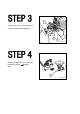
STEP 3 2 Connect the air hose (1) to the compressor’s air outlet (2) with the quick connector (3). 3 1 MC-589316-03 STEP 4 Close the tank drain valve (1), located on the bottom of the air tank.
STEP 5 Plug in the power cord (1). step 4 and 1 page 16, page 17, caution MC-589316-05 STEP 6 Set the pressure switch (1) to the ON position. 1 2 Turn the air pressure regulator knob (2) clockwise until desired pressure is reached.
QUICK START GUIDE TECHNICAL SPECIFICATIONS 3 SAFETY GUIDELINES 4–8 KEY PARTS DIAGRAM 9 IMPORTANT INFORMATION 10–12 ASSEMBLY INSTRUCTIONS 13–15 OPERATING INSTRUCTIONS 16–20 MAINTENANCE 21–23 TROUBLESHOOTING 24–25 EXPLODED VIEW 26 PARTS LIST 27 WARRANTY 28–29 8 U.S. GALLONS (30.
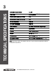
TECHNICAL SPECIFICATIONS 3 RUNNING HORSEPOWER 1.5 HP TANK SIZE 8 U.S. gallons (30.3 L) AIR DELIVERY (CFM*) @ 40 PSI 4.8 AIR DELIVERY (CFM*) @ 90 PSI 3.5 CUT-IN PRESSURE 105 PSI CUT-OUT PRESSURE 135 PSI PUMP DESIGN Oil-less, direct-drive, single-stage MOTOR 3,400 RPM POWER 120 V, 60 Hz, 12 A WEIGHT 57 lb 3 oz (26 kg) POWER CORD SJT 16 AWG / 72" (1.83 m) EXTENSION CORD SJT 12 AWG / Maximum 30' (9.
4 This manual contains information that relates to PROTECTING PERSONAL SAFETY and PREVENTING EQUIPMENT PROBLEMS. It is very important to read this manual carefully and understand it thoroughly before using the product. The symbols listed below are used to indicate this information. DANGER! Potential hazard that will result in serious injury or loss of life. WARNING! Potential hazard that could result in serious injury or loss of life.
SAFETY GUIDELINES 5 DANGER! Potential hazard that will result in serious injury or loss of life. • Risk of fire or explosion: Do not spray a flammable or combustible liquid or paint near sparks, flames, pilot lights or in a confined area. The spray area must be well-ventilated. Keep compressor at least 20’ (6 m) away from spray area. Do not carry and operate the compressor or any other electrical device near the spray area. Never smoke when spraying. Use a minimum of 25’ (7.
• Risk of burns: The pump and the manifold generate high temperatures. In order to avoid burns or other injuries, do not touch the pump, the manifold or the transfer tube while the compressor is running. Allow the parts to cool down before handling or servicing. Keep children away from the compressor at all times. • Risk to breathing: Be certain to read all labels when you are spraying paints or toxic materials, and follow all safety instructions.
7 SAFETY GUIDELINES WARNING! Potential hazard that could result in serious injury or loss of life. • The compressor must be located in a well-ventilated area for cooling, and must be a minimum of 12” (31 cm) away from the nearest wall. • Protect the air hose and the power cord from damage and puncture. Inspect them for weak or worn spots every week, and replace them if necessary. • Always wear hearing protection when using an air compressor. Failure to do so may result in hearing loss.
8 As the distance from the supply outlet increases, you must use a heavier gauge extension cord. Using extension cords with inadequately sized wire causes a serious drip in voltage, resulting in loss of power and possible product damage. Refer to the table to determine the required minimum wire size. Recommended Minimum Wire Gauge for Extension Cords* (120 V) CORD SIZE IN AWG (AMERICAN WIRE GAUGE) Extension cord length in feet AMPERE RATING 25' 50' 75' 100' 150' 200' 0-5 16 16 16 14 12 12 5.
KEY PARTS DIAGRAM 9 7 6 11 10 9 8 5 4 3 1 2 MC-589316-07 No. Description No. Description 1 Air tank 7 Outlet pressure gauge 2 Air tank drain valve 8 Tank pressure gauge 3 Power cord 9 Pressure switch 4 Air outlet 10 Electric motor 5 Air pressure regulator 11 Air compressor pump 6 Safety valve 8 U.S. GALLONS (30.
This Mastercraft® Air Compressor is ideal for a wide range of applications, from fastening to greasing and engine cleaning. The 8-gallon (30.3 L) design provides optimum pressure. It features a 1.5 HP induction motor for quiet operation and a cast-iron, oil-free pump for long-lasting, reliable performance. The procedures described in this manual are solely for this 8-gallon (30.3 L) air compressor at a maximum of P=135 PSI. The device has been designed / constructed for household use only.
11 IMPORTANT INFORMATION Pressure switch This switch turns the compressor on and off. It is operated manually and when it is in the ON position, it allows the motor to start if the pressure in the air tank is below the factory set cut-in pressure, and allows the motor to stop if the pressure in the air tank reaches the factory set cut-out pressure. Be sure to set this switch to the OFF position when the compressor is not being used and before unplugging the compressor.
12 Tool Compatibility Chart Operates Tool Continuously Air tool Operates Tool Intermittently Inflation/Recreation Brad Nailer (18-gauge) Finishing Nailer (16-gauge) 3-in-1 Brad/Finishing/Stapler Framing Nailer Roofing Nailer Flooring Nailer Impact Wrench Die Grinder Angle Grinder Air Ratchet Cut-off Tool Drill Hammer Chisel Shears Sander Polisher DIY Paint Sprayer Grease/Caulking Gun 8 U.S. GALLONS (30.
13 ASSEMBLY INSTRUCTIONS Assembly • Unpack the air compressor unit. Inspect the unit for damage. If the unit has been damaged, contact the retailer immediately. • Check the air compressor’s identification label to ensure that you have purchased the intended model and that it has the required pressure rating for its intended use. Packaging contents Description Qty. Air compressor 1 Owner’s manual 1 Air filter 1 Removable handle 1 Thumbscrews 1 Wheel kit 1 8 U.S. GALLONS (30.
14 Qty. Axle 2 Wheel 2 Washer 2 Lock washer 2 Nut 2 Illustration Tools required for assembly (not included): Accessory Qty. 11/16" open end wrench or 1 Adjustable wrench 1 Illustration 8 U.S. GALLONS (30.
15 Positioning of the air compressor ASSEMBLY INSTRUCTIONS 1. Position the air compressor (1) near an electrical outlet (2) (fig A). 2. The compressor must be at least 12" (31 cm) from any wall (3) or obstruction, in a clean, well-ventilated area to ensure sufficient air flow and cooling (fig A). 3. Place the air compressor on the floor or a hard, level surface. The air compressor must be level to ensure proper drainage of the moisture in the tank. fig A 2 1 3 MC-589316-09 Wheel assembly 4.
16 1. Set the pressure switch (1) to the OFF position (fig E). 2. Open the tank drain valve (1) by turning it counter-clockwise to permit the air to escape and prevent air pressure build-up in the air tank during the break-in period (fig F). fig E 1 MC-589316-13 fig F 1 3. Turn the air pressure regualtor knob (1) counter-clockwise until it stops (fig G). 4. Plug in the power cord (1) (fig H).
OPERATING INSTRUCTIONS 17 CAUTION! Potential hazard that may result in moderate injury or damage to equipment. • Use a dedicated circuit. The compressor will use the full capacity of a typical 15 A household circuit. If any other electrical devices are drawing from the compressor’s circuit, the air compressor may fail to start. Low voltage or an overloaded circuit can result in sluggish starting that causes the motor thermal overload protector or circuit breaker to trip, especially in cold conditions.
18 WARNING! Potential hazard that could result in serious injury or loss of life. • Risk of bursting. Too much air pressure causes a hazardous risk of bursting. Check the manufacturer's maximum pressure rating for air tools and accessories. The regulator outlet pressure must never exceed the maximum pressure rating. CAUTION! Potential hazard that may result in moderate injury or damage to equipment.
OPERATING INSTRUCTIONS 19 WARNING! Potential hazard that could result in serious injury or loss of life. • High temperatures are generated by the electric motor and the pump. To prevent burns or other injuries, DO NOT touch the air compressor while it is running. Allow it to cool before handling or servicing. Keep children away from the air compressor at all times. 4. Close the tank drain valve (1). Plug in the power cord (2) (fig M). fig M 2 5.
20 1. 2. 3. Set the pressure switch (1) to the OFF position (fig N). Unplug the power cord. Reduce the pressure in the tank through the outlet hose. Pulling the safety valve ring and keeping it open will also reduce the pressure in the tank. fig N 1 MC-589316-22 CAUTION! Potential hazard that may result in moderate injury or damage to equipment. • Escaping air and moisture can propel debris that may cause eye injury. Wear safety goggles when opening the drain valve.
21 MAINTENANCE General maintenance WARNING! Potential hazard that could result in serious injury or loss of life. • If any of the following symptoms appears while operating the product, stop using the product immediately, or serious personal injury could result. Only an authorized service centre should perform repairs on this product. • Disconnect the electrical plug and disconnect any tools from air supply before attempting any adjustment.
WARNING! Potential hazard that could result in serious injury or loss of life. • Be sure to wear protective goggles. • Relieve the air pressure in the system and open the drain valve on the bottom of the tank to drain. • Risk of bursting. Water will condense in the air tank. If not drained, water will corrode and weaken the air tank, causing a risk of air tank rupture. CAUTION! Potential hazard that may result in moderate injury or damage to equipment.
MAINTENANCE 23 WARNING! Potential hazard that could result in serious injury or loss of life. • Risk of bursting. If the safety valve does not work properly, over-pressurization may occur, causing air tank rupture or an explosion. Clean the air filter A dirty air filter will reduce air compressor performance and life. To avoid contaminating the pump, the filter should be cleaned frequently and replaced on a regular basis. Clean the foam filter by immersing it in warm, soapy water. Dry thoroughly after.
PROBLEM The motor will not run or start. The motor runs continuously when the pressure switch is in the ON position. POSSIBLE CAUSES SOLUTIONS 1. The power cord is not plugged in. 1. Plug the power cord into a grounded outlet. 2. The pressure switch is in the OFF position. 2. Set the pressure switch to the ON position. 3. The extension cord is the wrong wire gauge or is too long. 3. Check the technical specifications page 3 for the proper wire gauge and cord length. 4.
TROUBLESHOOTING 25 PROBLEM POSSIBLE CAUSES SOLUTIONS The regulator does not regulate the pressure. The regulator or its internal parts are dirty or damaged. Replace the regulator. The pressure is low or there is not enough air. There is moisture in the discharge air. The compressor overheats. 1. There is a leak at one of the fittings. 1. Check the fittings with soapy water. Tighten or reseal leaking fittings (apply plumber’s tape on threads). Do not overtighten. 2. The tank drain valve is open.
13 14 6 15 5 7 9 3 2 10 12 8 18 19 11 16 4 17 29 20 21 1 22 37 27 36 28 31 33 35 32 26 25 23 24 30 34 MC-589316-24 8 U.S. GALLONS (30.
27 PARTS LIST No. Description Qty. No. Description Qty. 1 Nut M10 4 20 Fan 1 2 Rubber foot 2 21 Air filter 1 3 Bolt M10x20 2 22 Back shroud 1 4 Drain valve 4 23 Bolt M5x18 4 5 Air tank 1 24 Self-tapping screw ST3.
28 3 This Mastercraft® product is guaranteed for a period of three (3) years from the date of original retail purchase against defects in workmanship and materials. Subject to the conditions and limitations described below, this product, if returned to us with proof of purchase within the stated warranty period and if covered under this warranty, will be repaired or replaced (with the same model, or one of equal value or specification), at our option.
WARRANTY 29 H. this warranty will not apply to normal deterioration of the exterior finish, such as, but not limited to, scratches, dents, paint chips, or to any corrosion or discolouring by heat, abrasive and chemical cleaners; I. this warranty will not apply to component parts sold by and identified as the product of another company, which shall be covered under the product manufacturer’s warranty, if any.