
Operator`s manual


10
11
S c r a p i n g
Blade
Paint & Varnish,
Bonded Carpet,
Soft Adhesives,
Vinyl Flooring,
wood and other
floor coverings.
2pcs
Sanding
Pad and
Sandpaper
Bare or painted
wood, plaster,
and other
surfaces,
depending on
sandpaper grit
1pc
sanding
pad+41pcs
sandpaper
(60
grits/120
grits/240
grits/320
grits -
8pcs of
each, 80
grits –
9pcs)
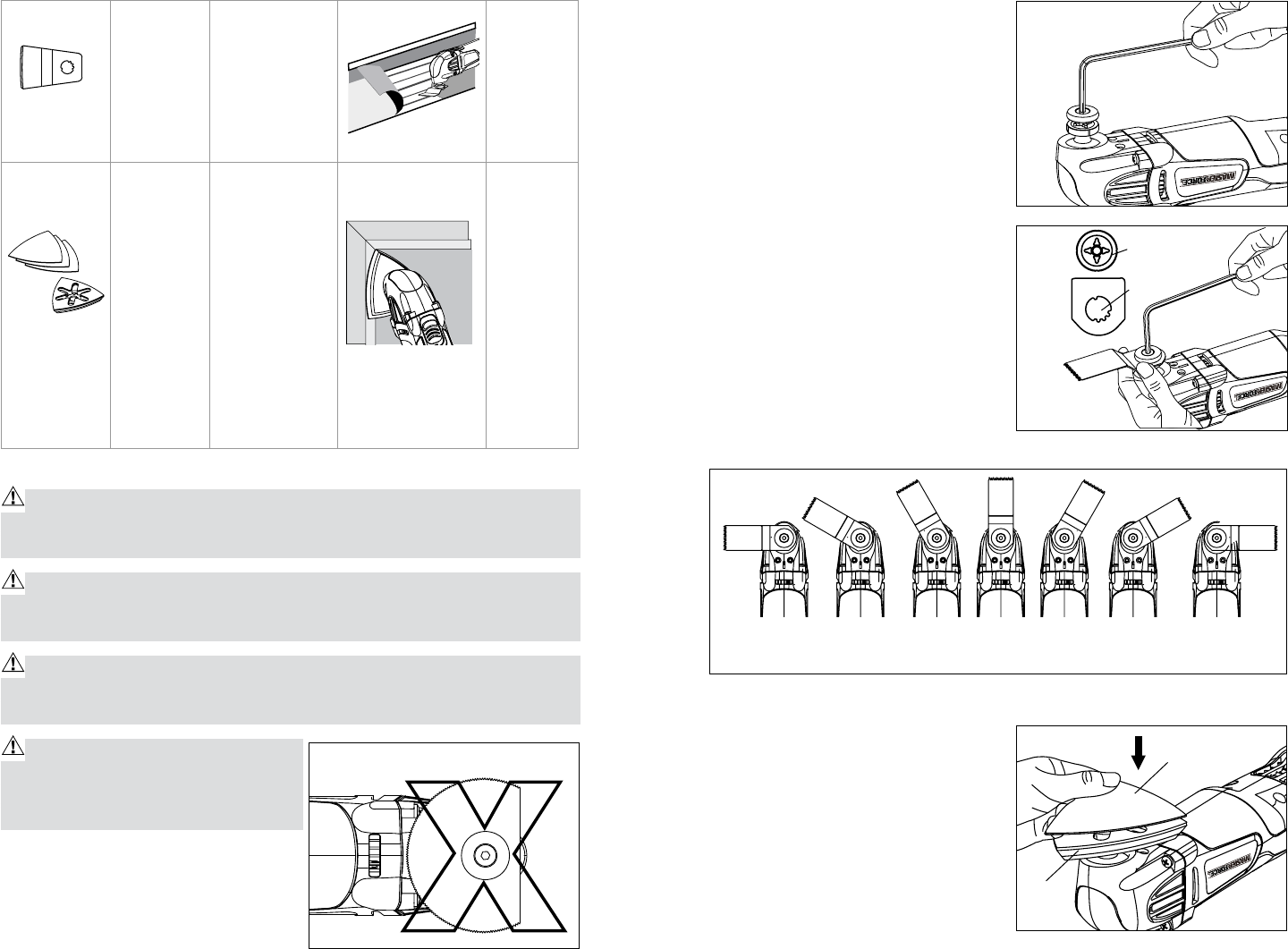
ATTACHING THE APPLICATION TOOL (Fig.4-7)
WARNING! Failure to disconnect the tool from power source when as-
sembling parts, making adjustments, or changing accessories could result in
accidental starting causing possibly serious injury.
CAUTION! For all work or when changing application tools, always wear
protective gloves. The sharp edges of the application tools will cause personal
injury. Application tools can be very hot while working.
WARNING! Check that the application tools are correctly attached. In-
correct or insecurely fastened application tools can come loose during oper-
ation and cause a hazard.
WARNING! Do not attach the Circu-
lar Grout or the Plunge Cut Saw Blade
facing backwards (Fig. 4), as operation
in this position may cause serious injury.
1. Disconnect the tool from the power
source.
2. Loosen the flange bolt with the hex
key supplied. (Fig. 5)
3. Ensure that the inner threads and
the drive shaft are clean.
4. Align the grooves on the application
tool with the four raised ribs on the
drive shaft; put the application tool
onto the drive shaft. (Fig.6)
5. With your gloved hand holding the
blade, put on and tighten the flange
bolt using the hex key.
NOTE: Attach the application tool at
the desired orientation for the task at
hand. The shaft is configured so that the
application tool can be attached every
30° around the shaft, from left 90° to
right 90°. (Fig.7)
MOUNTING/CHANGING THE
SANDPAPER (Fig.8)
1. Disconnect the tool from the power
source.
2. Follow the directions for Attaching
the Application Tool to attach the
sanding pad to the Utila-Tool
TM
.
3. Align the sandpaper with the
sanding pad and use your hand to
press it firmly on the sanding pad.
Fig.4
Fig.5
Fig.6
Ribs on shaft
Grooves
Fig.8
90
0
90
0
60
0
60
0
30
0
30
0
0
0
Fig.7
Sandpaper
Sanding
pad