Cordless String Trimmer 267-3293 OPERATOR’S MANUAL CAUTION: To Reduce the Risk of Injury, User Must Read and Understand the Operator’s Manual. Save These Instructions For Future Reference. For questions / comments, technical assistance or repair parts – Please Call Toll Free: 1-866-917-4374 (M-F 8:30am-5:00pm EST).
TABLE OF CONTENTS Safety Symbols. . . . . . . . . . . . . . . . . . . . . . . . . . . . . . . . . . . . . . . . . . . . . . . . . . . . . . . . . . Page 2 Safety Instructions. . . . . . . . . . . . . . . . . . . . . . . . . . . . . . . . . . . . . . . . . . . . . . . . . . . . . . . Page 3 Overview/Specifications . . . . . . . . . . . . . . . . . . . . . . . . . . . . . . . . . . . . . . . . . . . . . . . . . . Page 7 Assembly . . . . . . . . . . . . . . . . . . . . . . . . . . . . . . . . . . . . . . . . .
SAFETY SYMBOLS Some of these following symbols may be used on this tool. Please study them and learn their meaning. Proper interpretation of these symbols will allow you to operate the tool better and more safely. Symbol Name Designation / Explanation V Volts Voltage A Amperes Current Hz Hertz Frequency (cycles per second) no No-load speed Rotational speed at no load Per minute Revolutions, strokes, surface speed orbits, etc.
SAFETY INSTRUCTIONS The purpose of safety symbols is to attract your attention to possible dangers. The safety symbols, and the explanations with them, deserve your careful attention and understanding. The symbol warnings do not, by themselves, eliminate any danger. The instructions and warnings they give are no substitutes for proper accident prevention measures.
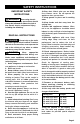
SAFETY INSTRUCTIONS IMPORTANT SAFETY INSTRUCTIONS WARNING: When using electric trimmers, basic safety precautions should always be followed to reduce the risk of fire, electric shock, and personal injury, including the following: READ ALL INSTRUCTIONS DANGER: Do not rely on the tool’s insulation against electric shock. To reduce the risk of electrocution, never operate the tool in the vicinity of any wires or cables which may carry electric current.
SAFETY INSTRUCTIONS 20. Do not open or mutilate the battery. Released electrolyte is corrosive and may cause damage to the eyes or skin. It may be toxic if swallowed. 21. Exercise care in handling batteries in order not to short the battery with conducting materials such as rings, bracelets, and keys. The battery or conductor may overheat and cause burns. 22. Do not operate the trimmer while under the influence of alcohol or drugs. 23. Clear the area to be cut before each use.
DANGER: People with electronic devices, such as pacemakers, should consult their physician(s) before using this product. Operation of electrical equipment in close proximity to a heart pacemaker could cause interference or failure of the pacemaker. WARNING: • Some dust created by power sanding, sawing, grinding, drilling, and other construction activities contains chemicals known to the state of California to cause cancer, birth defects, or other reproductive harm.
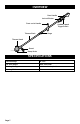
OVERVIEW Rear Handle Lock-off Button Front-assist Handle Variable-speed Trigger Switch Hinge Trimmer Shaft Trimmer Head Guard Bump Knob SPECIFICATIONS Rated Voltage 20 V d.c. No-load Speed 5800-7000 RPM Cutting-line Type 0.08 in. twisted nylon line Cutting Width 12 in.
ASSEMBLY CONTENTS WARNING: If any part is broken or missing, DO NOT attach the battery pack or operate the tool until the broken or missing part is replaced. Failure to do so could result in possible serious injury. WARNING: Do not attempt to modify this tool or create accessories not recommended for use with this tool. Any such alteration or modification is misuse and could result in a hazardous condition leading to possible serious injury.
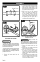
ASSEMBLY FIG. 2 2. Lift the trimmer head and face it upward; align the groove on the bottom of the guard with the raised portion on the base of the trimmer head, and then slide the guard onto the base (Fig 3). 3. Make sure that the two mounting holes in the guard are aligned with the two assembly holes in the base of the shaft. Insert a screw into each washer, and then lock the guard in place by tightening the two screws with a screwdriver (not included) (Fig 4). Hexagon Screws FIG. 4 Screw FIG.
ASSEMBLY TO ADJUST THE FRONT-ASSIST HANDLE POSITION The handle should be adjusted so that your front arm will be straight when using the trimmer. To adjust the front-assist handle position, loosen the screw knob so that the frontassist handle can be moved to the desired position of the shaft. Tighten the screw knob so that the handle cannot move on the shaft during operation. FIG. 5 Front-assist Handle TO ATTACH BATTERY PACK 1. Make sure that the switch is in the OFF position. 2.
OPERATION HOLDING THE STRING TRIMMER (FIG.7) TO START/STOP THE STRING TRIMMER (FIG.8) FIG. 8 FIG. 7 Lock-off Button Variable-speed Trigger Switch WARNING: Dress properly to reduce the risk of injury when operating this tool. Do not wear loose clothing or jewelry. Wear eye and ear/hearing protection. Wear heavy, long pants, boots, and gloves. Do not wear short pants or sandals or go barefoot.
OPERATION USING THE STRING TRIMMER FIG. 9 TIPS FOR BEST TRIMMING RESULTS WARNING: Direction of Rotation Best Cutting Area CHECK FOR DAMAGED/WORN PARTS BEFORE EACH USE WARNING: To prevent serious personal injury, remove the battery pack from the tool before servicing, cleaning, changing attachments or removing material from the unit. Check the bump head, guard and frontassist handle and replace any parts that are cracked, warped, bent, or damaged in any away.
OPERATION • Slowly move the trimmer into and out of the area being cut, maintaining the cutting head position at the desired cutting height. This movement can be either a forwardbackward motion or a side-to-side motion. Cutting shorter lengths produces best results. Always keep the trimming line fully extended. Line release becomes more difficult as the cutting line becomes shorter. WARNING: Do not remove or alter the line cutting blade assembly.
OPERATION LINE REPLACEMENT NOTICE: Always use triangle-shaped twisted nylon cutting line with a diameter that does not exceed 0.08 in. (2.0 mm). Using line other than that specified may cause the string trimmer to overheat or become damaged. WARNING: Never use metalreinforced line, wire, or rope, etc. These can break off and become dangerous projectiles.
OPERATION FIG. 11 FIG. 12 4.5 in. (11 cm) Tap FIG. 13 FIG. 14 n. ) 5 i cm .5 (12 FIG. 15 FIG.
MAINTENANCE WARNING: All maintenance should only be carried out by a qualified service technician. Before cleaning or performing any maintenance, remove battery from the tool. For safe and proper operation, always keep the tool and its ventilation slots clean. STORAGE Clean the tool thoroughly before storing it. Store the unit in a dry, well-ventilated area, locked-up or up high, out of the reach of children. Keep away from corrosive agents, such as garden chemicals and de-icing salts.
TROUBLESHOOTING PROBLEM CAUSE SOLUTION Tool does not work. Low battery capacity. Charge the battery pack. String trimmer stops while cutting. The motor shaft or trimmer head is bound with grass. Stop the trimmer, remove the battery, and remove the grass from the motor shaft and trimmer head. The motor is overloaded Move the trimmer head to cut the grass no more than 8 in. of length in a single cut. Remove the trimmer head from the grass and restart the tool.
Cordless String Trimmer WARRANTY 90-DAY MONEY BACK GUARANTEE: This MASTERFORCETM brand power tool carries our 90-DAY Money Back Guarantee. If you are not completely satisfied with your MASTERFORCETM brand power tool for any reason within ninety (90) days from the date of purchase, return the tool with your original receipt to any MENARDS® retail store, and we will provide you a refund – no questions asked.
© 2018 Menard, Inc.