/2” Impact Wrench P STO TO L AU H 241-0477 OPERATOR’S MANUAL CAUTION: To Reduce the Risk of Injury, User Must Read and Understand the Operator’s Manual. Save These Instructions For Future Reference. For questions / comments, technical assistance or repair parts – Please Call Toll Free: 1-866-917-4374 (M-F 8:30am-5:00pm EST).
TABLE OF CONTENTS Safety Symbols. . . . . . . . . . . . . . . . . . . . . . . . . . . . . . . . . . . . . . . . . . . . . . . . . . . . . . . . . . Page 2 Safety Instructions. . . . . . . . . . . . . . . . . . . . . . . . . . . . . . . . . . . . . . . . . . . . . . . . . . . . . . . Page 3 Overview/Specifications . . . . . . . . . . . . . . . . . . . . . . . . . . . . . . . . . . . . . . . . . . . . . . . . . . Page 7 Assembly . . . . . . . . . . . . . . . . . . . . . . . . . . . . . . . . . . . . . . . . .
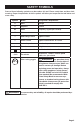
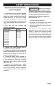
SAFETY SYMBOLS Some of these following symbols may be used on this tool. Please study them and learn their meaning. Proper interpretation of these symbols will allow you to operate the tool better and more safely.
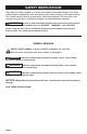
SAFETY INSTRUCTIONS The purpose of safety symbols is to attract your attention to possible dangers. The safety symbols and the explanations with them deserve your careful attention and understanding. The symbol warnings do not, by themselves, eliminate any danger. The instructions and warnings they give are no substitutes for proper accident prevention measures.
SAFETY INSTRUCTIONS GERNERAL POWER TOOL SAFETY WARNINGS WARNING: Read all safety warnings and instructions! Failure to follow the warnings and instructions may result in electric shock, fire and / or serious injury. Save all warnings and instructions for future reference. Save all warnings and instructions for future reference. The term “power tool” in the warnings refers to your mains-operated (corded) power tool or battery-operated (cordless) power tool. WORK AREA SAFETY 1.
SAFETY INSTRUCTIONS 6. Dress properly. Do not wear loose clothing or jewelry. Keep your hair, clothing and gloves away from moving parts. Loose clothes, jewelry or long hair can be caught in moving parts. 7. If devices are provided for the connection of dust extraction and collection facilities, ensure that these are connected and properly used. Use of these devices can reduce dust-related hazards. POWER TOOL USE AND CARE 1. Do not force the power tool. Use the correct power tool for your application.
SAFETY INSTRUCTIONS SPECIFIC SAFETY RULES FOR IMPACT WRENCH 1. Hold power tool by insulated gripping surfaces, when performing an operation where the cutting accessory may contact hidden wiring or its own cord. Cutting accessory contacting a “live” wire may make exposed metal parts of the power tool “live” and could give the operator an electric shock. 2.
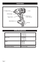
OVERVIEW 1/2” Square Driver Vents LED Worklight Direction-ofrotation Selector Trigger Switch TO L AU OP ST H Mode-Selector Belt Clip SPECIFICATIONS No-load Speed I:0-1100 RPM II:0-1600 RPM III:0-2200 RPM Impact Rate I:0-1500 BPM II:0-2500 BPM III:0-3000 BPM Torque I: 360 ft.lb II: 440 ft.lb III: 500 ft.lb Driver 1/2” Square Weight (Without battery) 3 lb. 5 oz. (1.
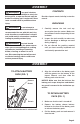
ASSEMBLY WARNING: If any part is broken or missing, DO NOT attempt to attach the battery pack, or operate the tool until the broken or missing part is replaced. Failure to do so could result in possible serious injury. WARNING: Do not attempt to modify this tool or create accessories not recommended for use with this tool. Any such alteration or modification is misuse and could result in a hazardous condition leading to possibly serious injury.
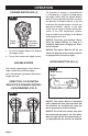
OPERATION TRIGGER SWITCH (FIG. 2) FIG. 2 Trigger Switch Directionof-rotation Selector 1. To turn the Impact Wrench on, depress the trigger switch. 2. To turn it off, release the trigger switch. VARIABLE SPEED The variable-speed trigger switch delivers higher speed with increased trigger pressure and lower speed with decreased trigger pressure. DIRECTION -OF-ROTATION SELECTOR (FORWARD/CENTERLOCK/REVERSE) (FIG.
OPERATION 1. Attach the battery pack to the Impact Wrench. 2. Position the direction-of-rotation selector to the left of the tool for forward rotation, and press the trigger switch to turn on the mode-indicator light. 3. Press the mode-selector button; the speed will change in three steps: low, medium and high. Press and hold the mode-selector button for three seconds: the auto-stop mode is available and the auto-stop indicator will be on.
OPERATION INSTALLING AND REMOVING THE SOCKET (FIG. 7) impact socket onto the nut or bolt head. 3. FIG. 7 Friction Ring Place the direction-of-rotation selector in the FORWARD position, and select a suitable speed or the auto-stop function. Hold the tool firmly while depressing the trigger switch. The impact socket will turn the fastener and the impacting action will begin when the fastener encounters resistance.
OPERATION Hold the tool firmly, and place the socket over the bolt or nut. Turn the tool on, and fasten the bolt or nut to the proper torque. The torque that is required to loosen a fastener averages 75% to 80% of the tightening torque, depending on the condition of the contacting surfaces. However, if rust or corrosion causes seizing, more torque may be required. After fastening, always check the torque with a torque wrench.
TROUBLESHOOTING PROBLEM CAUSE SOLUTION The Impact Wrench does not work. The battery is depleted. Charge the battery. The Impact Wrench does not work and the tool LED worklight flashes. The tool is overheated. Allow the tool to cool down. The impact wrench does not work and the battery pack LED light flashes. The battery is overheated. Allow the battery to cool down.
1/2” Impact Wrench WARRANTY 90-DAY MONEY BACK GUARANTEE: This MASTERFORCE® brand power tool carries our 90-DAY Money Back Guarantee. If you are not completely satisfied with your MASTERFORCE® brand power tool for any reason within ninety (90) days from the date of purchase, return the tool with your original receipt to any MENARDS® retail store, and we will provide you a refund – no questions asked.
© 2018 Menard, Inc.