/4” Impact Driver 241-0435 OPERATOR’S MANUAL CAUTION: To Reduce the Risk of Injury, User Must Read and Understand the Operator’s Manual. Save These Instructions For Future Reference. For questions / comments, technical assistance or repair parts – Please Call Toll Free: 1-866-917-4374 (M-F 8:30am-5:00pm EST).
TABLE OF CONTENTS Safety Symbols. . . . . . . . . . . . . . . . . . . . . . . . . . . . . . . . . . . . . . . . . . . . . . . . . . . . . . . . . . Page 2 Safety Instructions. . . . . . . . . . . . . . . . . . . . . . . . . . . . . . . . . . . . . . . . . . . . . . . . . . . . . . . Page 3 Overview/Specifications . . . . . . . . . . . . . . . . . . . . . . . . . . . . . . . . . . . . . . . . . . . . . . . . . . Page 7 Assembly . . . . . . . . . . . . . . . . . . . . . . . . . . . . . . . . . . . . . . . . .
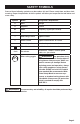
SAFETY SYMBOLS Some of these following symbols may be used on this tool. Please study them and learn their meaning. Proper interpretation of these symbols will allow you to operate the tool better and more safely.
SAFETY INSTRUCTIONS The purpose of safety symbols is to attract your attention to possible dangers. The safety symbols, and the explanations with them, deserve your careful attention and understanding. The symbol warnings do not, by themselves, eliminate any danger. The instructions and warnings they give are no substitutes for proper accident prevention measures.
SAFETY INSTRUCTIONS GENERAL POWER TOOL SAFETY WARNINGS WARNING: Read all safety warnings, instruction, illustrations and specifications provided with this power tool. Failure to follow all instructions listed below may result in electric shock, fire and/or serious injury. Save all warnings and instructions for future reference. The term “power tool” in the warnings refers to your mains-operated (corded) power tool or battery-operated (cordless) power tool.
SAFETY INSTRUCTIONS clothing away from moving parts. Loose clothes, jewelry or long hair can be caught in moving parts. g) If devices are provided for the connection of dust extraction and collection facilities, ensure these are connected and properly used. Use of dust collection can reduce dust-related hazards. h) Do not let familiarity gained from frequent use of tools allow you to become complacent and ignore tool safety principles. A careless action can cause severe injury within a fraction of a second.
SAFETY INSTRUCTIONS Battery pack Charger 252-8029 252-8025 252-8030 252-8036 252-8031 252-8037 252-8034 252-8044 252-8035 WARNING: Some dust created by power sanding, sawing, grinding, drilling and other construction activities contains chemicals known to the state of California to cause cancer, birth defects or other reproductive harm.
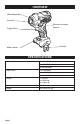
OVERVIEW LED Worklight Ring Chuck Direction-of-rotation Selector Trigger Switch Belt Clip Mode-selector SPECIFICATIONS No-load Speed I: 0-1,100 RPM II: 0-1,900 RPM III: 0-2,800 RPM Impact Rate I: 0-1,200 BPM II: 0-2,350 BPM III: 0-3,300 BPM Torque I: 770 in.lb II: 1,240 in.lb III: 1,700 in.lb Driver 1/4” Hex Weight 2 lb. 14 oz (1.
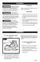
ASSEMBLY CONTENTS WARNING: If any part is broken or missing, DO NOT attach the battery pack or operate the tool until the broken or missing part is replaced. Failure to do so could result in possible serious injury. Cordless impact driver, bit holder, belt clip,bit and instruction manual. UNPACKING WARNING: Do not attempt to modify this tool or create accessories not recommended for use with this tool.
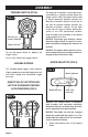
ASSEMBLY TRIGGER SWITCH (FIG.2) FIG. 2 Direction-ofrotation Selector Trigger Switch To turn the impact driver on, depress the trigger switch. The direction of rotation is reversible and is controlled by a selector located above the trigger switch. With the impact driver held in normal operating position: position the direction-of-rotation selector to the left of the tool for forward rotation; position the direction-of-rotation selector to the right of the tool for reverse rotation.
ASSEMBLY 2. Position the direction-of-rotation selector to the left of the tool for forward rotation, and press the trigger switch to turn on the mode-indicator light. 3. Press the mode selector to change the speed: press once for low, press twice for medium, and press a third time for high. 4. To make the Auto-stop function available, press and hold the mode selector for three seconds: the autostop indicator will shine.
OPERATION TO INSTALL THE BIT HOLDER (FIG.7): 1. Lock the trigger switch on the impact driver by placing the direction-ofrotation selector in the center position. FIG. 7 2. Insert the bit into the chuck. You will hear a “click” to indicate that the bit is securely installed in place. 3. Pull on the bit to check if it installed securely. REMOVING BITS Bit Holder 1. Lock the trigger switch on the impact driver by placing the direction-ofrotation selector in the center position. 2.
MAINTENANCE BEFORE EACH USE WARNING: Always wear safety goggles or safety glasses with side shields during power tool operations, or when blowing dust. If operation is dusty, also wear a dust mask. WARNING: Do not at any time allow brake fluids, gasoline, petroleum-based products, penetrating oils, etc. to come in contact with plastic parts. Chemicals can damage, weaken or destroy plastic, which may result in serious personal injury. 1. Check for damaged, missing, or worn parts. 2.
TROUBLESHOOTING PROBLEM The impact driver does not work. Page 13 CAUSE SOLUTION The battery pack is depleted. Charge the battery pack. The battery pack or impact driver is too hot. Turn off the impact driver and allow the impact driver and battery pack to cool.
1/4” Impact Driver WARRANTY 90-DAY MONEY BACK GUARANTEE: This MASTERFORCE® brand power tool carries our 90-DAY Money Back Guarantee. If you are not completely satisfied with your MASTERFORCE® brand power tool for any reason within ninety (90) days from the date of purchase, return the tool with your original receipt to any MENARDS® retail store, and we will provide you a refund – no questions asked.
© 2018 Menard, Inc.