
Technical data

15
8 Monitoring and control, Interfaces
MASTERGUARD Series SIII
UPS Systems from 60 to 800 kVA
MKA4CAT0UKSIII/Rev. 11-11/2004/UK
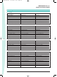
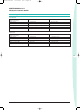
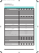
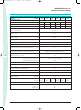
8.8 Available signalisations and
control signals
The UPS can handle up to 12
Input/Output control signals (8 inputs,
4 outputs) that can be programmed via
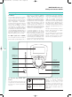
8.9 LIFE.net
In order to increase the overall
reliability of the system, Series S
III will
be delivered with the LIFE.net
communication kit, providing
connection to MASTERGUARD’s
LIFE.net monitoring service.
LIFE.net shall allow the remote
monitoring of the UPS through
telephone lines or GSM link in order to
ensure the maximum reliability of the
UPS throughout its operational life. The
monitoring shall be a real 24-hour, 365
day service thanks to a unique feature
that allows trained Service Engineers
to remain in constant electronic
contact with the service centre, and
therefore the UPS. The UPS shall
automatically dial-up the service
centre at defined intervals to provide
detailed information that shall be
analysed in order to predict near term
problems. In addition, it shall be
possible to control the UPS remotely.
The communication of UPS data to the
MASTERGUARD LIFE Command
Centre shall take be transmitted via
the integrated modem at the following
intervals:
•ROUTINE: settable at intervals o
between five minutes and two
days (typically once a day)
• EMERGENCY: when a problems
occurs or parameters are beyond
tolerance limits
• MANUAL: following a requestfrom
the command centre
During the call the command
centreshall:
• Identify the UPS connected
•Request the data stored in the UPS
memory since the last connection
•Request real-time information from
the UPS (selectable)
The service centre shall analyse
historical data and issue a regular
detailed report to the customer
informing him of the UPS operational
condition and any critical states.
The LIFE.net centre allows the
possibility of activating the LIFE-SMS
delivery system option, where the
customer may receive SMS
notification which will be activated in
the event of one of the following:
• Mains power failure
• Mains power recovery
•Reserve line failure
•Load supplied by reserve.
Fan (On-Off) In Battery Compartment Battery Fuse Monitor
Battery Compartment Overheated Micro Switch UPS Doors
Backfeed Protection Generator On
Hydrogen Present Remote Inverter Stop
SBS Bypass Switch Closed Insufficient Ventilation
SBS Output Switch Open
the display and/or PPVIS for a wide set
of functions. Emergency Power Off
(EPO) is programmed as standard: this
command electronically shuts down
the rectifier, the inverter and the
bypass switch. Listed below are the
most significant functions; the
exhaustive list is published in the User
Manual:
Tecnico-SIII-MG 10-11-2004 8:22 Pagina 15