
Users Manual Part 1


10
Product Install Guide – M4xx Series
03/11/22 | V1.9.9
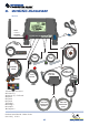
Permanent power supply feed (12/24V-DC)
- Provides Power to the system. Must be tted after circuit breaker
(if available).
Main Loom
Power (+) - RED
Ground (-) - BLACK
Ignition(+) - BROWN
POWER I/O CONNECTOR
Input/Output (see page 22)
Input 2 - WHITE
Input 3 - ORANGE
Input - YELLOW
Analog 1 - GREY
Analog 2 - PURPLE
Output 1 - GREEN
Output 2 - BLUE
Always refer and follow MICHELIN Connected Fleet’s recommendedPower (+), Ignition(+), and
Ground(-) connection points for the vehicle you are working on.
The recommended connection points are available:
• In the Vehicle guides, available on your job on Salesforce (Salesforce Guide)
• On the Master Manager Mobile (MMO) Install page (MMO guide)
• In the CAN-database, available through MMO (Link to MMO)
NOTE:
ALWAYS double check your connections with a multimeter as colours or wiring may change.
ALWAYS position the 5A fuses on the fused connections, power and ignition, as near to the
connection point as possible (do not extend the fuse wires).
ALWAYS connect the power supply to the feed rst and then to the OBU, to avoid electrical primers.
+POWER
Ignition Feed (12/24 V-DC)
- Must be connected to the ignition (2nd stage, still ON when
engine is running) and NEVER to the true engine idling feed (which
is only ON when engine is running).
(See page 10)
+IGNITION
- Must be connected directly to the chassis or a ground terminal.
NEVER use a self-tapping screw for a ground connection.
GROUND
VEHICLE SPECIFICS
7. Power Supply