
Users Manual Part 2


17
Product Install Guide – M4xx Series
03/11/22 | V1.9.9
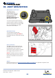
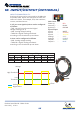
1. Open the CAN sensor.
There are four clips that you
need to undo.
2. There are two labelled
channels one for CAN High
and one for CAN Low.
3. Locate the CAN wire pair,
untwist them slightly.
4. Run the wires in the correct
labelled channels in the
sensor. They should NOT
cross over.
5. Close the sensor, taking
care to not damage or move
the wires, you should hear a
click. Secure the sensor with
one of the included cable
ties. Use the other cable tie
5-10cm further down to
relieve pressure on the wires.
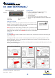
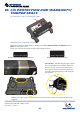
The MICHELIN Connected Fleet CAN sensors are unintrusive to the vehicle CAN and have
read only functionality. This means that the CAN sensors can’t input any data on to the
network that might cause issues with the vehicle. Ignition MUST be o while connecting the
CAN clips.
The clips come in two varieties:
• CAN, white label Sonde SCN4
• J1587, green label Sonde SCN4
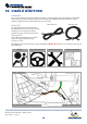
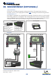
Depending on the vehicle make and model you might require one or two CAN sensors. Most vehicles
only require one clip. This means that your CAN setup will look like one of these
three options:
• CAN; one white labelled sensor
• CAN+CAN; two white labelled sensors
• CAN+J1587; one white labelled sensor and one green labelled sensor
NOTE: A J1587, green label, sensor will work as a replacement for a CAN, white label, sensor. However
the green clip should only be used when needed.
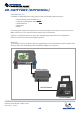
NOTE: The CANClip must be installed
behind the dash trim of the vehicle and
not accessible to the end user (driver).
12. CAN (Optional)
1
2
3
4
5