
Users Manual Part 2


23
Product Install Guide – M4xx Series
03/11/22 | V1.9.9
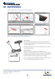
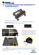
Main Loom
Power (+) - RED
Ground (-) - BLACK
Ignition(+) - BROWN
Input/Output
Input 2 - WHITE
Input 3 - ORANGE
Input 4 - YELLOW
Analog 1 - GREY
Analog 2 - PURPLE
Output 1 - GREEN
Output 2 - BLUE
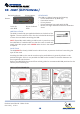
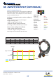
INPUT COMPATIBILITY
A variety of inputs can be connected to the M4xx via
the power loom. Inputs are connected to check the
status of a device, for example; PTO, door switches,
reverse, and beacons etc.
3 (4 if you count ignition) wires can be congured
as follows:
I/O Wire Compatibility
Input 1 Input 2 Input 3 Input 4 Analog 1 Analog 2
Voltage
Time
High Threshold
Low
Threshold
Analog Value
Digital Value
• TOR - (On/O control) standard digital
voltage reading (0 or 1)
• CAD - Analog voltage reading
• TOR/CAD - Digital reading translated
according to the thresholds up and down.
2 wires can be congured as follows:
• CAD - Analog voltage reading
• TOR/CAD - Digital reading translated
according to the thresholds up and down.
18. Input/Output (Optional)
TOR X X X X
CAD X X X X X X
TOR/CAD
X X X X X X