CHARGEMASTER PLUS 12/75-3, 12/100-3, 24/40-3, 24/60-3 ALL-IN-ONE BATTERY CHARGER USER AND INSTALLATION MANUAL EN NL DE FR ES IT 10000015492/07 For the latest version of this manual, visit our website: Ga om deze handleiding in andere talen te downloaden naar onze website: Um diese Anleitung in anderen Sprachen herunterzuladen, besuchen Sie bitte unsere Website: Pour télécharger ce manuel dans d'autres langues, consultez notre site Web : Para descargar este manual en otros idiomas, visite nuestro sitio web
ChargeMaster Plus 12/75-3, 12/100-3, 24/40-3, 24/60-3 – User and Installation Manual TABLE OF CONTENTS 1 GENERAL INFORMATION ......................... 3 1.1 Use of this manual ................................... 3 1.2 Liability ...................................................... 3 1.3 Warranty .................................................... 3 1.4 Disclaimer ................................................. 3 1.5 Identification label .................................... 3 1.
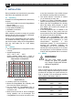
ChargeMaster Plus 12/75-3, 12/100-3, 24/40-3, 24/60-3 – User and Installation Manual 3 1 GENERAL INFORMATION 1.1 Use of this manual This manual serves as a guideline for the safe and effective operation and maintenance of the following ChargeMaster Plus models: derived from this document. Please consult our most current Terms & Conditions of Sale. 1.
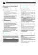
ChargeMaster Plus 12/75-3, 12/100-3, 24/40-3, 24/60-3 – User and Installation Manual 2 SAFETY INSTRUCTIONS IMPORTANT SAFETY INSTRUCTIONS SAVE THESE INSTRUCTIONS WARNING! Read the entire manual before using the ChargeMaster Plus. Keep this manual in a secure place. This chapter describes important safety and operating instructions for use of a ChargeMaster Plus in residential, recreational vehicle (RV) and marine applications. 2.
ChargeMaster Plus 12/75-3, 12/100-3, 24/40-3, 24/60-3 – User and Installation Manual BATTERIES GENERATE EXPLOSIVE GASES DURING NORMAL BATTERY OPERATION. FOR THIS REASON, IT IS OF UTMOST IMPORTANCE THAT EACH TIME BEFORE USING THE ChargeMaster Plus, YOU READ THIS MANUAL AND FOLLOW THE INSTRUCTIONS EXACTLY. 2 To reduce risk of battery explosion, follow these instructions and those published by battery manufacturer and manufacturer of any equipment you intend to use in vicinity of the battery.
ChargeMaster Plus 12/75-3, 12/100-3, 24/40-3, 24/60-3 – User and Installation Manual 2.7 When battery is installed in vehicle A SPARK MAY CAUSE BATTERY EXPLOSION. To reduce risk of a spark near battery: 1 Position AC and DC cords to reduce risk of damage by hood, door, or moving engine part. 2 Stay clear of fan blades, belts, pulleys, and other parts that can cause injury to persons. 3 Check polarity of battery posts.
ChargeMaster Plus 12/75-3, 12/100-3, 24/40-3, 24/60-3 – User and Installation Manual battery by referring to car owner’s manual and make sure it matches output rating of battery charger. 2.10 Grounding instructions This battery charger should be connected to a grounded, metal, permanent wiring system; or an equipment-grounding conductor should be run with circuit conductors and connected to equipment-grounding terminal or lead on battery charger.
ChargeMaster Plus 12/75-3, 12/100-3, 24/40-3, 24/60-3 – User and Installation Manual 3 INSTALLATION During installation and commissioning, the safety instructions are applicable at all times. 3.1 Unpacking In addition to the ChargeMaster Plus the delivery includes: • Mounting bracket to mount the ChargeMaster Plus to a wall; • Battery temperature sensor; • Drop cable CZone/MB (1m); • MasterBus Terminator; • User manual. After unpacking, check the contents for possible damage.
ChargeMaster Plus 12/75-3, 12/100-3, 24/40-3, 24/60-3 – User and Installation Manual Use the following wire colors for DC wiring color or at least different colors to make a clear distinction between the positive and negative wire from the battery: Wire color Red Black Meaning Positive Negative Connect to: + (POS) – (NEG) Run the positive and negative cables next to each other to limit the electromagnetic field around the cables.
ChargeMaster Plus 12/75-3, 12/100-3, 24/40-3, 24/60-3 – User and Installation Manual devices, forming a local data network. Both networks need a terminating device on both ends of the network. Do not make ring networks or T-connections. • CZone network Points to consider: ˗ Up to 40 devices can be connected together on a single backbone. ˗ Make sure the CZone network has two terminating resistors, one at each open end of the backbone.
ChargeMaster Plus 12/75-3, 12/100-3, 24/40-3, 24/60-3 – User and Installation Manual 3.
ChargeMaster Plus 12/75-3, 12/100-3, 24/40-3, 24/60-3 – User and Installation Manual 3.7 Connection example This schematic illustrates the general placement of the ChargeMaster Plus in a circuit. It is not meant to provide detailed wiring instructions for any particular electrical installation. Figure 3: Installation drawing of the ChargeMaster Plus Notes: - If the battery temperature remains within 15-25°C, connection of the battery temperature sensor is optional.
ChargeMaster Plus 12/75-3, 12/100-3, 24/40-3, 24/60-3 – User and Installation Manual WARNING! 13 2 All electrical systems (AC and DC) must be disconnected from any power source during the entire installation! CAUTION! Too-thin cables and/or loose connections can cause dangerous overheating of the cables and/or terminals. Therefore, tighten all connections well, in order to limit transition resistance as far as possible. Use cables of the correct size.
ChargeMaster Plus 12/75-3, 12/100-3, 24/40-3, 24/60-3 – User and Installation Manual 5 Connect the wiring to the screw terminals. Fasten the cable with the strain relief. 7 Attach the battery temperature sensor to the casing of battery bank 1. Plug the temperature sensor cable into the “Temp sense” jack. 6 Integrate a fuse holder in the positive battery wire but do not place the fuse yet! Fit crimp-on cable lugs to the DC cables.
ChargeMaster Plus 12/75-3, 12/100-3, 24/40-3, 24/60-3 – User and Installation Manual 9 If required, use a small screwdriver to change DIP switch settings. See section 4.1. 15 3.9 Commissioning after installation 1 Check the wiring; positive connected to positive (red cables), negative connected to negative (black cables). 2 When all wiring is OK, place the DC fuse(s) to connect the batteries to the ChargeMaster Plus. WARNING! 10 Check all wiring; see also Figure 3 for wiring details.
ChargeMaster Plus 12/75-3, 12/100-3, 24/40-3, 24/60-3 – User and Installation Manual 4 SETTINGS Adjustment of the settings of the ChargeMaster Plus can be made in two different ways: • By means of DIP switches. • From a laptop or notebook connected to the ChargeMaster Plus via a USB Interface. Some settings can only be changed in this way. CAUTION! In a MasterBus network: DIP switch 1 must always be set to the ON position (1). DIP switch 2 is MasterBus Powering ON (1) or OFF (0).
ChargeMaster Plus 12/75-3, 12/100-3, 24/40-3, 24/60-3 – User and Installation Manual 4.2.1 17 Monitoring A remote panel, like the SmartRemote, Touch 5 (CZone) or EasyView 5 (MasterBus), can be used for reading battery information. See applicable user manuals for details. The following table lists the parameters as shown in MasterAdjust.
4.2.2 ChargeMaster Plus 12/75-3, 12/100-3, 24/40-3, 24/60-3 – User and Installation Manual Alarms The following table lists the available alarms in MasterAdjust. Parameter Meaning Alarm status Bat. temp. error Battery temperature too high / too low TS error Temperature sensor error DC 1 OUT Shunt mismatch Setting for nominal voltage (12/24V) at the MasterShunt or the nominal voltage of the MLI batteries differs from nominal voltage detected by the ChargeMaster Plus.
ChargeMaster Plus 12/75-3, 12/100-3, 24/40-3, 24/60-3 – User and Installation Manual 4.2.4 19 Configuration settings The configuration can be done in MasterAdjust, from a laptop or notebook connected to the ChargeMaster Plus via a Mastervolt USB Interface. See applicable user manuals for details. The following table lists the parameters as shown in MasterAdjust. Notes: - DIP switch settings overrule MasterBus settings.
ChargeMaster Plus 12/75-3, 12/100-3, 24/40-3, 24/60-3 – User and Installation Manual Parameter Bulk Voltage Minimum time Start time at Maximum time Absorption Voltage Maximum time Return Amps Minimum time Float Voltage Return to bulk V Return to bulk sec DC 1 OUT Name Shunt device DC 2 OUT Name DC 3 IN/OUT Name Installer menu DIP Switch Factory settings button Meaning Factory setting Value range Bulk voltage (@ 25°C); see section 5.
ChargeMaster Plus 12/75-3, 12/100-3, 24/40-3, 24/60-3 – User and Installation Manual 4.2.5 21 Events – System automation A CZone/MasterBus device can be programmed to initiate an action at another connected device. This is very helpful in automation of your system but is not required. In MasterBus this is done by means of event-based commands. In the Events tab you can program the ChargeMaster Plus to act as an event source.
4.2.6 ChargeMaster Plus 12/75-3, 12/100-3, 24/40-3, 24/60-3 – User and Installation Manual Current control If the available power at the AC input is limited. The ChargeMaster can be configured to reduce input current. The Current Control level should be set equal to or lower than the value of the external circuit breaker, which protects the incoming AC power. For example, when the external AC power is limited by a 6A fuse, the Current Control level should be set to ≤6A.
ChargeMaster Plus 12/75-3, 12/100-3, 24/40-3, 24/60-3 – User and Installation Manual 23 4.5 CZone configuration The CZone® network is an NMEA 2000-compliant CAN-based system. When the ChargeMaster Plus is connected, open the CZone Configuration Tool on a Windows laptop or notebook connected to the CZone network. Either do the configuration while connected to the network or use a prepared configuration file (.zcf). Ensure that a DIP Switch is assigned.
ChargeMaster Plus 12/75-3, 12/100-3, 24/40-3, 24/60-3 – User and Installation Manual 9. NMEA2000 Instances are used to differentiate between multiple monitoring sources. 10. Press OK to return to the Module Modification window and press the Alarm/Switch Settings button. 11. Select the required Alarm Severities. 12. Press OK. Optionally configure digital switching by adding Circuit Controls in the Circuits tab (e.g. a battery low switch can be used to start a generator).
ChargeMaster Plus 12/75-3, 12/100-3, 24/40-3, 24/60-3 – User and Installation Manual 25 5 OPERATING INSTRUCTIONS 5.1 Introduction The Mastervolt ChargeMaster Plus is a fully automatic battery charger. This means that under normal circumstances it can be left switched on with AC power and batteries connected. The ChargeMaster Plus is suitable for charging of Li-ion and lead-acid batteries, which may include maintenance-free, low maintenance, AGM, gel or deep-cycle batteries.
3 4 5 ChargeMaster Plus 12/75-3, 12/100-3, 24/40-3, 24/60-3 – User and Installation Manual Blinking fast green Blinking slow green Solid green Blinking fast green Blinking slow green Solid green Blinking green Battery in bulk stage Battery absorption stage Battery in float stage Battery in bulk stage Battery absorption stage Battery in float stage Network communication OUTPUT POWER MENU LED State Meaning 1 Solid orange Output power menu Total output power 02 Solid orange 25% Total output power 263
ChargeMaster Plus 12/75-3, 12/100-3, 24/40-3, 24/60-3 – User and Installation Manual 5.4.1 Charge voltages AGM or GEL Flooded Lithium-ion 5.4.2 Bulk 14.25 / 28.5 14.25 / 28.5 14.25 / 28.5 5.4.4 Flat battery support Absorption Float 14.25 / 13.80 / 28.5 27.6 14.25 / 13.25 / 28.5 26.5 14.25 / 13.50 / 28.5 27.0 Pre-float The ChargeMaster Plus can automatically switch each individual output from absorption to prefloat stage.
ChargeMaster Plus 12/75-3, 12/100-3, 24/40-3, 24/60-3 – User and Installation Manual 5.5 DC 3 IN/OUT The ChargeMaster Plus is equipped with three outputs; DC 1 OUT, DC 2 OUT and DC 3 IN/OUT. The total output current is divided over these three outputs. See section 3.6 for connections. DC 3 IN/OUT can be current limited and can serve as an output and as an input to charge batteries 1 & 2.
ChargeMaster Plus 12/75-3, 12/100-3, 24/40-3, 24/60-3 – User and Installation Manual 5.6 Maintenance No specific maintenance to the ChargeMaster Plus is required. Examine your electrical installation on a regular basis, at least once a year. Defects such as loose connections, damaged wiring etc. must be corrected immediately. If necessary, use a soft clean cloth to clean enclosure of the ChargeMaster Plus.
ChargeMaster Plus 12/75-3, 12/100-3, 24/40-3, 24/60-3 – User and Installation Manual 6 TROUBLE SHOOTING The ChargeMaster Plus is protected against overload, short circuit, overheating and under and over voltage. If a fault condition occurs, the LEDs indicate an error code. See section Status display for an explanation. CAUTION! The ChargeMaster Plus is not protected against serious over voltage (>275VAC) on the AC input.
ChargeMaster Plus 12/75-3, 12/100-3, 24/40-3, 24/60-3 – User and Installation Manual 31 Malfunction Possible cause What to do Batteries are discharged too fast Battery capacity reduced due to wastage or sulphation, stagnation Charge and recharge a few times, this might help.
ChargeMaster Plus 12/75-3, 12/100-3, 24/40-3, 24/60-3 – User and Installation Manual 7 TECHNICAL DATA 7.1 Specifications 12V models Model Product code Nominal input voltage Nominal input frequency Full load consumption Max. AC input current (@ 240VAC) Max. AC input current (@ 120VAC) Nominal output voltage Total charge current* Number of battery outlets Max. current DC 3 IN/OUT Max.
ChargeMaster Plus 12/75-3, 12/100-3, 24/40-3, 24/60-3 – User and Installation Manual 7.2 33 Specifications 24V models Model Product code Nominal input voltage Nominal input frequency Full load consumption Max. AC input current (@ 230VAC) Max. AC input current (@ 120VAC) Nominal output voltage Total charge current* Number of battery outlets Max. current DC 3 IN/OUT Max. input voltage DC 3 IN/OUT Charge characteristic* Charge voltage Bulk* Charge voltage Absorption* Charge voltage Float*; Max.
7.3 ChargeMaster Plus 12/75-3, 12/100-3, 24/40-3, 24/60-3 – User and Installation Manual Dimensions Dimensions in mm [inches] ChargeMaster Plus models 12/75-3, 12/100-3, 24/40-3 and 24/60-3. Characteristics Output power (%) 7.
ChargeMaster Plus 12/75-3, 12/100-3, 24/40-3, 24/60-3 – User and Installation Manual Figure 9: 3-step+ charging characteristics of flooded batteries 35
Copyright © 2020 Mastervolt. All rights reserved. Reproduction, transfer, distribution or storage of part or all of the contents in this document in any form without the prior written permission of Mastervolt is prohibited. Europe, Middle East & Africa Customer Service T: +31 (0) 20 34 22 100 E: info@mastervolt.com Americas & Caribbean Customer Service T: +1 800 307 6702, Option 1 E: orderentry@marinco.com Asia Pacific Customer Service T: +64 9 415 7261 Option 1 E: enquiries@bepmarine.