GEBRUIKERSHANDLEIDING / USERS MANUAL BETRIEBSANLEITUNG / MODE D’EMPLOI MASS 12/30-2, 24/15-2, 24/25-2 battery charger 1 General information . . . . . . . . . . . . . . . . . . . . . . . . . . . . . . . . . . . . . . . . . . . . . . . . . . . . . . . . . . .10 2 Safety guidelines & measures . . . . . . . . . . . . . . . . . . . . . . . . . . . . . . . . . . . . . . . . . . . . . . . . . . .10 3 Technical data . . . . . . . . . . . . . . . . . . . . . . . . . . . . . . . . . . . . . . . . . . . . . . .
GENERAL INFORMATION 1 / SAFETY GUIDELINES EN MEASURES GENERAL INFORMATION GARANTEE SPECIFICATIONS Mastervolt quarantees the performance of this Mass charger according to the specifications given in the data sheets, if installed and used as described in this manual.
TECHNICAL DATA / TECHNOLOGY 3 TECHNICAL DATA GENERAL Model Function apparatus Manufacturer MASS 12/30-2 battery charger/rectifier Mastervolt, Amsterdam MASS 24/15-2 MASS 24/25-2 INPUT Voltage Frequency Current Power factor Efficiency 230V, -10% +15% 50/60 Hz, ± 5 Hz 2.5A 1 88% 230V AC, -10% +15% 50/60 Hz, ± 5 Hz 2.5A 1 88% 230V, -10% +15% 50/60 Hz, ± 5 Hz 3.
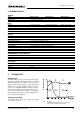
TECHNOLOGY / INSTALLATION Phase 1: Main charge (“BULK”) The first step “BULK” starts after switching on the MASS charger. In this phase, the charger supplies the maximum current until the battery reaches 14.40V. The battery is now 80% charged. When the battery reaches this limitation area the charge current wil decrease. Bulk duration is maximum 6 hours, depending on the battery’s condition and charge rate. The yellow “bulk” LED on the front panel will light up during this phase.
INSTALLATION WIRING AND CONNECTIONS When connecting any auxiliary equipment and/or a battery isolator, proceed as follows: • switch off the charger; • switch off the AC mains or generator supply; • isolate the DC distribution from the battery. Steps: 1 2 3 Battery wires Keep the cable connection between charger and battery as short as possible. If possible use coloured battery cables. I f this is not possible, mark the plus and the minus cables with coloured insulating tape, e.g.
INSTALLATION / OPERATION / USING THE CHARGER WITH YOUR BATTERIES Switching off: The IVO charger will be switched off by the OFF switch. 7 Forced float For industrial applications only. Gel/wet battery By removing this jumper the output will be a constant “trickle charge” voltage of 13,8V. Diode compensation By removing this jumper the output voltage will be increased with 0,7 Volt.
TROUBLE SHOOTING 8 TROUBLE SHOOTING Malfunction Possible cause What to do No output voltage and/or current No AC mains or fuse blowes Check fuse, replace if necessary. Mains or generator output too low Check input voltage, must be between 190 and 260V (nominal 230V). Battery load consumes more than the charger can supply, the battery voltage cannot increase more Reduce the battery load taken from batteries.
MAINTENANCE 9 / EC DECLARATION MAINTENANCE The battery charger requires no specific maintenance. For a reliable and optimal function of the MASS battery charger only the following is required: • Check at least ones a year the wire and cable connections (loosen joints etc.). • Keep the MASS charger dry, clean and in a dust-free area, in order to ensure a good heat discharge.
APENDIX A & B MASS 12/30-2, 24/15-2, 24/25-2 battery charger MASTERVOLT Snijdersbergweg 93, 1105 AN Amsterdam, The Netherlands Tel. +31-20-3422100 / Fax +31-20-6971006 V1.
34
DATA SHEETS 11 DATA SHEETS MASS 12/30-2 MAIN INFORMATION Design Manufacturer Model / name Product Article no Colour : : : : : : Weight excl. packing Shipping weight Cabinet typ Dimensions Carton dimensions Type of packing Available Availability : : : : : : : : by MASTERVOLT ISO 9001 certified MASS 12/30-2 battery charger/rectifier 04-00-10300 • RAL 5021, wasserblau • RAL 7037, grey 2.6 kg 4 kg MASS 1 cabinet hxwxd. 325 x 220 x 111 mm hxwxd.
DATA SHEETS TECHNICAL SPECIFICATIONS Short circuit proctection Reverse polarity protection Over heat : yes, reduced output max. 30 Amps : yes, by internal fuses : yes, derating output and shut off by 80°C temperature on heatsink Storage temperature Operating ambient temperature Humidity Vibration Cooling Forced cooling Environmental protection : : : : : : : Reliability/life time : • MTBF 30.
DATA SHEETS Main PCB of the MASS 12/30-2. New ‘high tech’ enclosure.
DATA SHEETS • Temperature variation 5.0 mV/°C per cell • Reference voltage 25°C • Battery charging is not allowed above +50°C and under -20°C • 12 Volt 30 mV/°C • 24 Volt 60 mV/°C 5.0 mV/°C Uref 25°C flo at ge l/w et ba tte dio ry de co m pe ns at ion Setpoint 30 sec. 30 mV/C 30 sec. 12.80 V 360 min. 15 min. 2.5 Amps 30 Amps 14.40 V 14.25 V 13.25 V 13.25 V 550 mV 600 mV 15.00 V 14.50 V 10.00 V 11.00 V 30 sec. ed Set points register Min.
DATA SHEETS DATA SHEETS MASS 24-15-2 MAIN INFORMATION Design Manufacturer Model / name Product Article no Colour : : : : : : Weight excl. packing Shipping weight Cabinet type Dimensions Carton dimensions Type of packing Available Availability : : : : : : : : by MASTERVOLT ISO 9001 certified MASS 24/15-2 battery charger/rectifier 04-00-20150 • RAL 5021, wasserblau • RAL 7037, grey 2.6 kg 4 kg MASS 1 cabinet hxwxd. 325 x 220 x 111 mm hxwxd.
DATA SHEETS TECHNICAL SPECIFICATIONS Short circuit proctection : yes, reduced output max. 15 Amps Reverse polarity protection : yes, by internal fuses Over heat : yes, derating output and shut off by 80°C temperature on heatsink Storage temperature Operating ambient temperature Humidity Vibration Cooling Forced cooling Environmental protection : : : : : : : -25°C to 80°C -20°C to 40°C, derating with 2.
DATA SHEETS Main PCB of the MASS 24/15-2. New ‘high tech’ enclosure.
DATA SHEETS Setpoint 30 sec. 60 mV/C 30 sec. 25.60 V 360 min. 15 min. 1.25 Amps 15 Amps 28.70 V 28.50 V 26.50 V 26.50 V 1.10 V 600 mV 30 V 29 V 20 V 22 V 30 sec. • Temperature variation 5.0 mV/°C per cell • Reference voltage 25°C • Battery charging is not allowed above +50°C and under -20°C • 12 Volt 30 mV/°C • 24 Volt 60 mV/°C 5.0 mV/°C flo at ge l/w et ba tte dio ry de co m pe ns at ion Uref 25°C ed Set points register Min.
DATA SHEETS 11 DATA SHEETS MASS 24/25-2 MAIN INFORMATION Design Manufacturer Model / name Product Article no Colour : : : : : : Weight excl. packing Shipping weight Cabinet type Dimensions Carton dimensions Type of packing Available Availability : : : : : : : : by MASTERVOLT ISO 9001 certified MASS 24/25-2 battery charger/rectifier 04-00-20250 • RAL 5021, wasserblau • RAL 7037, grey 2.6 kg 4 kg MASS 1 cabinet hxwxd. 325 x 220 x 111 mm hxwxd.
DATA SHEETS TECHNICAL SPECIFICATIONS Short circuit proctection : yes, reduced output max. 25 Amps Reverse polarity protection : yes, by internal fuses Over heat : yes, derating output and shut off by 80°C temperature on heatsink Storage temperature Operating ambient temperature Humidity Vibration Cooling Forced cooling Environmental protection : : : : : : : -25°C to 80°C -20°C to 40°C, derating with 2.
DATA SHEETS Main PCB of the MASS 24/25-2. ACCESSORIES Article no 04-15-00100 --04-15-00300 --00-17-05000 -- & REMOTES description basic remote control standaard remote contol advanced remote control MASS 1 temperature sensor MASS 1 cable set MASS 1 remote cable set Adjustment Interface Smart alarm control box New ‘high tech’ enclosure.
DATA SHEETS Setpoint 30 sec. 60 mV/C 30 sec. 25.60 V 360 min. 15 min. 1.25 Amps 25 Amps 28.70 V 28.50 V 26.50 V 26.50 V 1.10 V 600 mV 30 V 29 V 20 V 22 V 30 sec. • Temperature variation 5.0 mV/°C per cell • Reference voltage 25°C • Battery charging is not allowed above +50°C and under -20°C • 12 Volt 30 mV/°C • 24 Volt 60 mV/°C 5.0 mV/°C flo at ge l/w et ba tte dio ry de co m pe ns at ion Uref 25°C ed Set points register Min.
NOTES NOTES Apendix B 47
C-3-RS panel code part number 07-04-03040 MASTERVISION MODULAR SWITCHBOARDS SPECIFICATIONS CAUTION 1. Lethal voltages exist on your vessel. Make sure all shore power, onboard generating sources and batteries are disconnected before beginning installation of your electrical panel. description: type: remote standard charger control for Mass & IVO smart chargers 2. AC modules will have lethal voltages on the bus bars and terminals.
C-4-RB panel code part number 07-04-04100 MASTERVISION MODULAR SWITCHBOARDS SPECIFICATIONS CAUTION 1. Lethal voltages exist on your vessel. Make sure all shore power, onboard generating sources and batteries are disconnected before beginning installation of your electrical panel. description: type: remote basic charger control for Mass & IVO smart chargers 2. AC modules will have lethal voltages on the bus bars and terminals.
NOTES NOTES 50 September 1999 / MASS 12/30, 24/15 and 24/25 battery charger / EN
Charger Control float absorption on - bulk charge current output failure external current control Charger Charger Control Control float Inverter Control Charger Control Charger Output on on on failure absorption failure float failure DC alarm normally closed normally open common CSI alarm normally closed normally open common 6 pole telephone jack RJ 45 absorption float on - bulk charge bulk absorption failure bulk external LED failure external LED bulk external LED 20-40% current control external LE