iB6 & iB12 Integrated Temperature Controller User Guide smart hot runner solutions www.mastip.
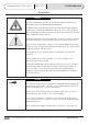
Temperature Controller iB6 / iB12 1.0 Introduction Precautions WARNING Use of this equipment in a manner not specified by the manufacturer may impair protection provided by the equipment. In addition to presenting a potential fire hazard, high voltage and high temperature can damage equipment and cause severe injury or death. When installing or using this instrument, follow all instructions carefully and use approved safety controls. Hazardous potentials exist on components inside the controller.
1.0 Introduction iB6 / iB12 Temperature Controller Table of Contents 4 pg Contents 6 6 6 9 10 12 12 13 14 14 15 15 16 18 18 18 18 18 19 20 20 20 21 22 24 25 26 29 29 29 30 31 32 32 32 33 33 33 1.0 1.1 1.2 1.4 2.0 3.0 3.1 3.2 3.3 3.4 3.5 3.6 3.7 4.0 4.1 4.2 4.3 4.4 4.5 5.0 5.1 5.2 5.3 5.4 5.5 5.6 5.7 6.0 6.1 6.2 6.3 6.4 7.0 7.1 7.2 8.0 8.1 8.
Temperature Controller iB6 / iB12 1.0 Introduction Table of Contents pg Contents 34 34 35 36 37 38 39 40 41 42 9.0 9.1 9.2 9.3 9.4 9.5 9.6 9.7 9.8 10.
1.0 Introduction iB6 / iB12 Temperature Controller 1.1 About this User Guide This user guide contains all the information needed to configure and operate the iB6 and iB12 Integrated Temperature Controllers. Wiring diagrams, mounting instructions and other information about installing the hardware are on the installation diagrams shipped with the unit. 1.2 iB6 & iB12 Features and Benefits 1.2.
Temperature Controller 1.2.2 iB6 / iB12 1.0 Introduction PID Control with Autotuning When an iB6 or iB12 zone is in Normal (closed loop) mode, Proportional-Integral-Derivative (PID) control is provided. The iB6 and iB12 Temperature Controllers also support Manual (open loop) mode that overrides automatic control. In Manual mode you control the output by entering a fixed output percentage value.
1.0 Introduction 1.2.4 iB6 / iB12 Temperature Controller Programmable Boost Function Every iB6 and iB12 Temperature Controller supports a boost function. For each zone you can use the Boost Config menu to configure a special setpoint (closed loop boost) or a special fixed output percentage (open loop boost) to be used when the boost button is pressed.
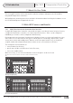
Temperature Controller iB6 / iB12 1.0 Introduction 1.4 What Happens When You Power Up the Controller When an iB6 or iB12 Temperature Controller is powered up using the switch on the back, all LEDs and all elements in the LCD display light briefly, and then software versions (of the display and the controller hardware) are displayed. At the conclusion of the startup process, the process values and setpoints for all zones are displayed.
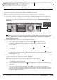
2.0 Setup Sequence iB6 / iB12 Temperature Controller 2.1 Setup Sequence The following list summarises the configuration and startup tasks to be accomplished once the controllers are wired as shown on the diagrams shipped with the unit. Refer to Section 5 for information about all configuration parameters, parameter interactions and valid ranges. 1) Turn on the controller using the switch on the back (shown below). When the unit is powered up, the controller goes through its startup sequence (see 1.
Temperature Controller 2.0 Setup Sequence iB6 / iB12 d) Change the unit of measure by pressing e) Exit the menu system by pressing and holding for several seconds. The PV and SP for all zones (except any offline zones) will be displayed in the selected unit of measure. Other temperature values previously entered while a different unit of measure was in use will be converted automatically. or . 4) If the factory settings listed in subsection 3.
3.0 User Interface iB6 / iB12 Temperature Controller for Manual (closed loop) for Standby If the zone is configured to start up in Idle after the run/idle button status LED will be lit. Whenever a zones output is on, its green output has been pressed, no LED is lit. 3.1 Overview During operation, the front panel contains a two-line display that displays the PV (process value) and SP (Normal (closed loop) mode setpoint or Manual (open loop) mode output percentage) for each zone during normal operation.
Temperature Controller 3.0 User Interface iB6 / iB12 3.2 LED Status and Button Functions 3.2.1 LED Symbols A column of LEDs for each zone indicates statuses for the zone and its output. LED 3.2.
3.0 User Interface iB6 / iB12 Temperature Controller 3.3 Selecting One or All Zones To select one zone, press repeatedly until only that zones PV and SP are displayed. To select all zones, press repeatedly until the PV and SP for all zones are displayed with asterisks between the PV and SP for zones 3 and 4 (see right) on an iB6, and between zones 3 and 4, and zones 9 and 10 on an iB12. 250 250 248 250 3.4 Mode of Operation 3.4.
Temperature Controller 3.4.4 iB6 / iB12 3.
3.0 User Interface iB6 / iB12 Temperature Controller 3.7 Configuration Menus and Factory Settings The table below shows all configuration menus, the parameters in each menu, and the factory settings. Information about each parameter is in Section 5. At the factory, all zones settings are identical. When a parameter is accessed, the display of its name alternates with the display of its current value.
Temperature Controller Menu Parameters Factory Setting Display Config Display Units °C 6 Alarm Config Inhibit Seconds 0 (off) High Dev Setpoint [High Deviation] 17 °C (30 °F) Low Dev Setpoint [Low Deviation] 17 °C (30 °F) Alarm Silence Seconds 120 seconds—applies to all zones Set Superv.
4.0 Alarms & Alarm Indication iB6 / iB12 Temperature Controller 4.1 Types of Alarms The iB6 and iB12 Temperature Controllers support high and low deviation alarms, configurable separately for each zone (see subsection 5.6). The unit also recognises process problems (such as loop break, reversed and open sensors, and process temperature exceeding configured safety limit) and problems with its own operation. 4.
Temperature Controller iB6 / iB12 4.0 Alarms & Alarm Indication 4.5 Alarm Priorities If a zone has more than one alarm condition, the code for the highest-priority alarm is displayed. Alarm priorities are in the table below.
5.Parameter Characteristics iB6 / iB12 Temperature Controller 5.1 Introduction This section contains information about every configuration parameter, including valid ranges, control mode(s) to which the parameter applies and interactions among parameters. For an overview of configuration menus and parameters refer to Section 3.7. 5.2 Input Parameters 5.2.
Temperature Controller iB6 / iB12 5.0 Parameter Characteristics 5.3 Boost Parameters 5.3.1 Introduction A boost button s on the iB6 and iB12 front panel. When you press be increased temporarily. , the output of a zones will You can use the Boost Config menu to specify: • whether the boost function will be closed loop (based on a setpoint) or open loop (based on a specified output percent) • boost setpoint and duration for closed loop boost • boost output percentage and duration for open loop boost 5.
5.0 Parameter Characteristics iB6 / iB12 Temperature Controller 5.4 Control Parameters 5.4.
Temperature Controller Name Applies to iB6 / iB12 Open Loop Control Closed Loop Control All Zones Selected Zones Range/ Choices 5.
5.
Temperature Controller 5.5.2 iB6 / iB12 5.
5.0 Parameter Characteristics 5.6.
Temperature Controller 5.7.2 iB6 / iB12 5.0 Parameter Characteristics Supervisor Parameters and Settings Name Applies to Open Loop Control Closed Loop Control All Zones Selected Zones Set Superv. Password Range/ Choices 100 to 999 Default Description & Interactions 100 = Off Password needed to access parameters in Superv [Supervisor] Config menu Fail Safe Action Off Auto Average Fixed Output Pct.
5.0 Parameter Characteristics 5.7.2 Temperature Controller Supervisor Parameters and Settings Name Applies to Enable Gradual increase of output to slowly dissipate moisture in heaters; refer to 1.2.3 Mode Key Enable Disable Enable Enable Boost Key Enable Disable Enable Enable Enables/disables SP Change Enable Disable Enable Enable Enables/disables use of front panel buttons to change Normal mode setpoint and Manual mode output percentage Config.
Temperature Controller iB6 / iB12 6.0 PID Controller Tuning 6.1 Introduction iB6 and iB12 Temperature Controllers support automatic tuning for control of zones running in CompuCycle Normal (closed loop) mode. By default, every iB6 and iB12 controller is configured to execute the Autotune operation the first time it is powered up, then to disable the Autotune feature, even if Autotune was not successful.
6.0 PID Controller Tuning iB6 / iB12 Temperature Controller During the Autotune operation, the display for the selected zones blinks “Tun.” Unless you want to terminate the Autotune by changing a zones mode, do not press any buttons during the Autotune operation. The lower line will continue to display the setpoint you entered in Step 2.
Temperature Controller iB6 / iB12 6.0 PID Controller Tuning 6.4 Manual Tuning (Zeigler-Nichols PID Method) 6.4.1 Introduction This tuning method may be used if the spread between initial process temperature and process operating temperature is small, or if the process is too slow for Autotuning. Manual tuning requires that zones be tuned one at a time and that the PV be tracked over time. (Graph the displayed PV against time manually.) All zones should be running while manually tuning one zone.
7.0 Restricting Functions iB6 / iB12 Temperature Controller 7.1 Introduction If you have access to the Superv [Supervisor] Config menu, you can disable any of the following: the soft start feature (not recommended), boost button , mode button , use of the front-panel buttons to change setpoints or configuration parameters. 7.2 Procedure To disable/enable a button or function: 1) Select any zone by pressing .
Temperature Controller 8.0 Resetting Default Values iB6 / iB12 8.1 Introduction Using this function returns all configuration parameter values for the selected zone(s) to their defaults (shown in Section 5). The setpoints for the selected zone(s) will be changed to 25 °C (77 °F). Reloading defaults never affects the following settings that apply to the whole controller: display units, input type.
9.0 Wiring iB6 / iB12 Temperature Controller 9.1 CE 16 Pin Female Power Connector for iB6 Zone 1 2 3 4 5 6 6 Zone, 16 Pin Mould Connector Pin Number Connection 1 Power 9 Return 2 Power 10 Return 3 Power 11 Return 4 Power 12 Return 5 Power 13 Return 6 Power 14 Return Ground 34 © Copyright Mastip Technology Limited. Information subject to alteration. V1.02 www.mastip.
Temperature Controller 9.0 Wiring iB6 / iB12 9.2 CE 16 Pin Male Thermocouple for iB6 Zone 1 2 3 4 5 6 6 Zone, 16 Pin Mould Connector Pin Number Connection 1 Thermcouple + 9 Thermcouple - 2 Thermcouple + 10 Thermcouple - 3 Thermcouple + 11 Thermcouple - 4 Thermcouple + 12 Thermcouple - 5 Thermcouple + 13 Thermcouple - 6 Thermcouple + 14 Thermcouple Ground © Copyright Mastip Technology Limited. Information subject to alteration. V1.02 www.mastip.
9.0 Wiring iB6 / iB12 Temperature Controller 9.3 US Domestic 25 Pin Female Power Connector 10A Max for iB6 1 A C Zone 1 2 3 4 5 6 2 3 4 5 6 7 8 9 B 6 Zone, 25 Pin Mould Connector Pin Number Connection A1 Power A2 Return A3 Power A4 Return A5 Power A6 Return A7 Power A8 Return B2 Power B3 Return B4 Power B5 Return Ground 36 © Copyright Mastip Technology Limited. Information subject to alteration. V1.02 www.mastip.
Temperature Controller 9.0 Wiring iB6 / iB12 9.4 US Domestic 25 Pin Male Thermocouple Connector for iB6 1 2 3 4 5 6 7 8 9 B Zone 1 2 3 4 5 6 A C 6 Zone, 25 Pin Mould Connector Pin Number A1 Connection Thermocouple + A2 Thermocouple - A3 Thermocouple + A4 Thermocouple - A5 Thermocouple + A6 Thermocouple - A7 Thermocouple + A8 Thermocouple - B2 Thermocouple + B3 Thermocouple - B4 Thermocouple + B5 Thermocouple Ground © Copyright Mastip Technology Limited.
9.0 Wiring iB6 / iB12 Temperature Controller 9.5 CE 24 Pin Female Power Connector for iB12 Zone 1 2 3 4 5 6 7 8 9 10 11 12 12 Zone, 24 Pin Mould Connector Pin Number Connection 1 Power 13 Return 2 Power 14 Return 3 Power 15 Return 4 Power 16 Return 5 Power 17 Return 6 Power 18 Return 7 Power 19 Return 8 Power 20 Return 9 Power 21 Return 10 Power 22 Return 11 Power 23 Return 12 Power 24 Return Ground 38 © Copyright Mastip Technology Limited.
Temperature Controller 9.0 Wiring iB6 / iB12 9.
9.0 Wiring iB6 / iB12 Temperature Controller 9.
Temperature Controller 9.0 Wiring iB6 / iB12 9.
10.
Temperature Controller M MAN mode indicator, 14 Manual mode, 7, 11, 14, 15, 16, 18, 21, 28 Manual Mode Boost, 14 manual tuning procedure, 28, 30, 31 manual tuning, when required, 28, 30, 31 menu button, 13 mode button, 13, 15, 29, 30, 32 Mode Key Enable parameter, 17, 28 modes of operation, 14 N Normal mode, 11, 14, 15, 16, 17, 18, 21, 27, 28, 29 Normal Mode Boost, 14 Normal Soft Start mode, 13, 14 NRB mode indicator, 14 NRM mode indicator, 14, 30 NSS mode indicator, 14 NTU mode indicator, 14, 30 O OF
smart hot runner solutions Mastip Head Office New Zealand 558 Rosebank Road Avondale, Auckland 1026 PO Box 90-651 Victoria Street West Auckland 1142 New Zealand Phone: +64 9 970 2100 Fax: +64 9 970 2070 Email: mastip@mastip.com Mastip Regional Office Europe Phone: +33 4 724 72 800 Fax: +33 4 724 72 801 Email: europe@mastip.com Mastip Regional Office China Phone: +86 21 644 77838 Fax: +86 21 644 77828 Email: china@mastip.