
User`s guide
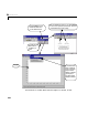
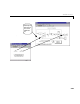
Table Of Contents
- Preface
- Quick Start
- LTI Models
- Introduction
- Creating LTI Models
- LTI Properties
- Model Conversion
- Time Delays
- Simulink Block for LTI Systems
- References
- Operations on LTI Models
- Arrays of LTI Models
- Model Analysis Tools
- The LTI Viewer
- Introduction
- Getting Started Using the LTI Viewer: An Example
- The LTI Viewer Menus
- The Right-Click Menus
- The LTI Viewer Tools Menu
- Simulink LTI Viewer
- Control Design Tools
- The Root Locus Design GUI
- Introduction
- A Servomechanism Example
- Controller Design Using the Root Locus Design GUI
- Additional Root Locus Design GUI Features
- References
- Design Case Studies
- Reliable Computations
- Reference
- Category Tables
- acker
- append
- augstate
- balreal
- bode
- c2d
- canon
- care
- chgunits
- connect
- covar
- ctrb
- ctrbf
- d2c
- d2d
- damp
- dare
- dcgain
- delay2z
- dlqr
- dlyap
- drmodel, drss
- dsort
- dss
- dssdata
- esort
- estim
- evalfr
- feedback
- filt
- frd
- frdata
- freqresp
- gensig
- get
- gram
- hasdelay
- impulse
- initial
- inv
- isct, isdt
- isempty
- isproper
- issiso
- kalman
- kalmd
- lft
- lqgreg
- lqr
- lqrd
- lqry
- lsim
- ltiview
- lyap
- margin
- minreal
- modred
- ndims
- ngrid
- nichols
- norm
- nyquist
- obsv
- obsvf
- ord2
- pade
- parallel
- place
- pole
- pzmap
- reg
- reshape
- rlocfind
- rlocus
- rltool
- rmodel, rss
- series
- set
- sgrid
- sigma
- size
- sminreal
- ss
- ss2ss
- ssbal
- ssdata
- stack
- step
- tf
- tfdata
- totaldelay
- zero
- zgrid
- zpk
- zpkdata
- Index
6 The LTI Viewer
6-58
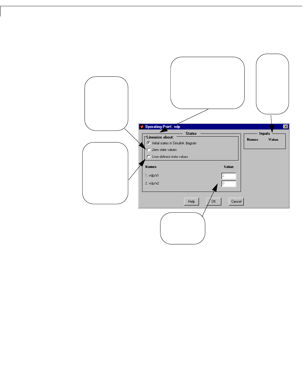
1 Select Set Operating Point in the Simulink menu. This opens the
Operating Point window.
Figure 6-24: The Operating Point Window for Changing Linearization Points
2 Change the rad io button selectio n to either:
- Set all state valu es f or the line arization to ze ro.
- Define your o wn state values for the linearizati on.
3 Use the white textboxes to specify the operating conditions for each input
(and state) listed in the
Operating Poin t window. Y ou don’t have to specify
the states if you choose the
Zero state values radio button.
The default setting for the Operating
Point
window uses initial states from
the Simulink diagram. Select either of
the other two radio buttons to set all
state values for linearization to zero,
or choose some other values.
Edit the operating
point values in the
textboxes provided.
When you select this
radio button, the
Simulink LTI Viewer
uses zero state
values for each
linearization.
When you select this
radio button, the
Simulink LTI Viewer
uses the values in the
textboxes for each
linearization, unless
you change these.
When you
have inputs in
your Simulink
model, you
can set
linearization
values for
them here.