
User`s guide

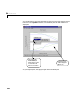
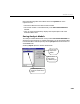
Table Of Contents
- Preface
- Quick Start
- LTI Models
- Introduction
- Creating LTI Models
- LTI Properties
- Model Conversion
- Time Delays
- Simulink Block for LTI Systems
- References
- Operations on LTI Models
- Arrays of LTI Models
- Model Analysis Tools
- The LTI Viewer
- Introduction
- Getting Started Using the LTI Viewer: An Example
- The LTI Viewer Menus
- The Right-Click Menus
- The LTI Viewer Tools Menu
- Simulink LTI Viewer
- Control Design Tools
- The Root Locus Design GUI
- Introduction
- A Servomechanism Example
- Controller Design Using the Root Locus Design GUI
- Additional Root Locus Design GUI Features
- References
- Design Case Studies
- Reliable Computations
- Reference
- Category Tables
- acker
- append
- augstate
- balreal
- bode
- c2d
- canon
- care
- chgunits
- connect
- covar
- ctrb
- ctrbf
- d2c
- d2d
- damp
- dare
- dcgain
- delay2z
- dlqr
- dlyap
- drmodel, drss
- dsort
- dss
- dssdata
- esort
- estim
- evalfr
- feedback
- filt
- frd
- frdata
- freqresp
- gensig
- get
- gram
- hasdelay
- impulse
- initial
- inv
- isct, isdt
- isempty
- isproper
- issiso
- kalman
- kalmd
- lft
- lqgreg
- lqr
- lqrd
- lqry
- lsim
- ltiview
- lyap
- margin
- minreal
- modred
- ndims
- ngrid
- nichols
- norm
- nyquist
- obsv
- obsvf
- ord2
- pade
- parallel
- place
- pole
- pzmap
- reg
- reshape
- rlocfind
- rlocus
- rltool
- rmodel, rss
- series
- set
- sgrid
- sigma
- size
- sminreal
- ss
- ss2ss
- ssbal
- ssdata
- stack
- step
- tf
- tfdata
- totaldelay
- zero
- zgrid
- zpk
- zpkdata
- Index
6 The LTI Viewer
6-60
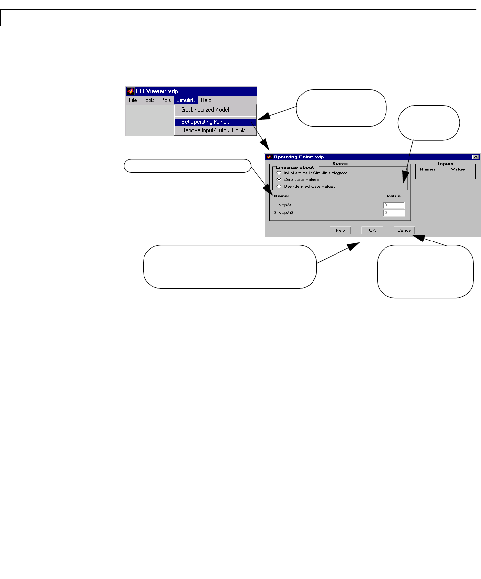
For this e xample, we use the Zero initial states setting, shown in the figure
below.
Note the following:
• The inputs listed on the
Operating Point window correspond to the Inport
blocks on the top level of your Simulink model.
• All states and inputs in the Simulink diagram are listed in this window, not
just those associated with your analysis model.
• If you w ant t o change the operating conditions, you need only change those
values associated with your analysis model.
• While the
Operating Point window is in the User-defined initial state
values
mode, the values listed in the Operating Point window remain in
effect throughout your Simulink LTI Viewer session unless you change
these.
Choose this menu on the
Simulink LTI Viewer to set
the operating conditions.
Simulink path name for the state variables
Selecting OK opens a dialog box, asking you to accept
the changes you made to the operating conditions and
linearize the model with these operating conditions.
Edit the operating
point values here.
Selecting Cancel closes this
window without
implementing any changes
to the operating conditions.