
User`s manual

8 Serial Port I/O
8-10
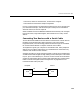
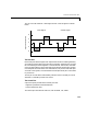
The RTS and CTS Pins. The RTS and CTS pins are used to signal whether the
devices are ready to send or receive data. This type of data flow control – called
hardware handshaking – is used to prevent data loss during transmission.
When enabled for both the DTE and DCE, hardware handshaking using RTS
and CTS follows these steps:
1 The DTE asserts the RTS pin to instruct the DCE that it is ready to receive
data.
2 The DCE asserts the CTS pin indicating that it is clear to send data over the
TD pin. If data can no longer be sent, the CTS pin is unasserted.
3 The data is transmitted to the DTE over the TD pin. If data can no longer be
accepted, the RTS pin is unasserted by the DTE and the data transmission
is stopped.
To enable hardware handshaking in MATLAB, refer to “Controlling the Flow
of Data: Handshaking” on page 8-59.
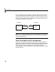
The DTR and DSR Pins. Many devices use the DSR and DTR pins to signal if they
are connected and powered. Signaling the presence of connected devices using
DTR and DSR follows these steps:
1 The DTE asserts the DTR pin to request that the DCE connect to the
communication line.
2 The DCE asserts the DSR pin to indicate it’s connected.
3 DCE unasserts the DSR pin when it’s disconnected from the communication
line.
The DTR and DSR pins were originally designed to provide an alternative
method of hardware handshaking. However, the RTS and CTS pins are usually
used in this way, and not the DSR and DTR pins. However, you should refer to
your device documentation to determine its specific pin behavior.
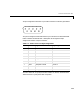
The CD and RI Pins. The CD and RI pins are typically used to indicate the
presence of certain signals during modem-modem connections.
CD is used by a modem to signal that it has made a connection with another
modem, or has detected a carrier tone. CD is asserted when the DCE is