
User`s guide

3 Working with Signals
3-94
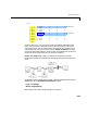
•Set the Output signal parameter of the Frame Status Conversion block to
Sample-based.
Notice that the current value of the Simulink timer (from the Digital Clock
block) is prepended to each output frame. The frame-based signal is converted
to a sample-based signal by the Frame Status Conversion block so that the
output in the command window will be easily readable.
In the example, the Signal From Workspace block generates a new frame
containing four samples once every second (T
fo
=¼∗4). The first few output
frames are shown below.
(t=0)
[ 1 2 3 4]
(t=1) [ 5 6 7 8]
(t=2) [ 9 10 11 12]
(t=3) [13 14 15 16]
(t=4) [17 18 19 20]
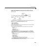
The Upsample block upsamples the input by a factor of 4, inserting three zeros
between each input sample. The change in rates is confirmed by the Probe
blocks in the model, which show a decrease in the frame period from T
fi
= 1 to
T
fo
= 0.25.
Question: When does the first input sample appear in the output?
The “Latency and Initial Conditions” section of the reference page for the
Upsample block indicates that when Simulink is in multitasking mode, the
first sample of the block’s frame-based input appears in the output as
sample M
i
L+D+1, where M
i
is the input frame size, L is the Upsample factor,
and D is the
Sample offset. This formula therefore predicts that the first input
in this example should appear as output sample 17 (i.e., 4
∗4+0+1).
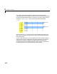
To verify this, look at the output from the simulation, saved in the workspace
array
yout. To convert the array to a easier-to-read matrix format, type
squeeze(yout)'
The first few samples of the result, ans, are shown below.