
User`s guide


Dyadic Analysis Filter Bank
5-155
Applications
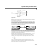
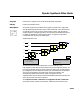
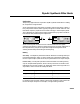
Wavelets. The primary application for dyadic analysis filter banks is coding for
data compression using wavelets.
At the transmitting end, the output of the dyadic analysis filter bank is fed to
a lossy compression scheme, which typically assigns the number of bits for each
filter bank output in proportion to the relative energy in that frequency band.
This represents the more powerful signal components by a greater number of
bits than the less powerful signal components.
At the receiving end, the transmission is decoded and fed to a dyadic synthesis
filter bank to reconstruct the original signal. The filter coefficients of the
complementary analysis and synthesis stages are designed to cancel aliasing
introduced by the filtering and resampling.
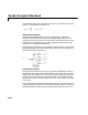
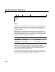
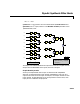
Scalograms. When the magnitudes in each of the subband signals y
k
, 1 ≤ k ≤ n,
are plotted across the full bandwidth of the original signal, the result is a
scalogram. This is the equivalent of a spectrogram with constant Q, where
and is the midpoint frequency of the band occupied by output y
k
. The
frequency axis of a scalogram therefore has logarithmic divisions like those
shown below, where F
s
is the sample rate (1/T
s
).
T
fi
=1
T
si
=1/64
T
so
=1/32)
T
so
=1/16)
T
so
=1/8)
T
so
=1/8)
T
fo
= 1
lossy
coding
decoding
Q
f
y
k
BW
y
k
--------------=
f
y
k