
User`s guide

FIR Rate Conversion
5-207
5FIR Rate Conversion
Purpose Upsample, filter, and downsample an input signal.
Library Filtering / Multirate Filters
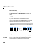
Description The FIR Rate Conversion block resamples the discrete-time input to a period
K/L times the input sample period, where the integer K is specified by the
Decimation factor parameter and the integer L is specified by the
Interpolation factor parameter. The resampling process consists of the
following steps:
•The block upsamples the input to a higher rate by inserting L-1 zeros
between input samples.
•The upsampled data is passed through a direct-form II transpose FIR filter.
•The block downsamples the filtered data to a lower rate by discarding K-1
consecutive samples following each sample retained.
K and L must be relatively prime integers; that is, the ratio K/L cannot be
reducible to a ratio of smaller integers. The FIR Rate Conversion block
implements the above three steps together using a polyphase filter structure,
which is more efficient than straightforward upsample-filter-decimate
algorithms. The output of the interpolator is the first filter phase, while the
output of the decimator is the last filter phase. When both K and L are greater
than 1, the resulting output is the last decimation phase from the first
interpolation phase.
The
FIR filter coefficients parameter specifies the numerator coefficients of
the FIR filter transfer function H(z).
The coefficient vector,
[b(1) b(2) ... b(m)], can be generated by one of the
filter design functions in the Signal Processing Toolbox (such as
fir1), and
should have a length greater than the interpolation factor (m>L). The filter
should be lowpass with normalized cutoff frequency no greater than
min(1/L,1/K). All filter states are internally initialized to zero.
Hz() Bz() b
1
b
2
z
1–
… b
m
z
m 1–()–
+++==