
User`s guide

Variable Fractional Delay
5-493
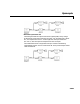
Delay values less than 0 are clipped to 0, and delay values greater than D are
clipped to D, where D is the
Maximum delay. Note that a delay value of 0
causes the block to pass through the current input sample,
U(1), in the same
simulation step that it is received.
FIR Interpolation Mode. In FIR Interpolation mode, the block computes a value
for the sample at the desired delay by applying an FIR filter of order 2P to the
stored samples on either side of the desired delay, where P is the
Interpolation
filter half-length
. For periodic signals, a larger value of P (i.e., a higher order
filter) yields a better estimate of the sample at the specified delay. A value
between 4 and 6 for this parameter (i.e. a 7th to 11th order filter) is usually
adequate.
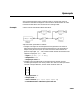
A vector of 2P filter tap weights is precomputed at the start of the simulation
for each of Q-1 discrete points between input samples, where Q is specified by
the
Interpolation points per input sample parameter. For a delay
corresponding to one of the Q interpolation points, the unique filter computed
for that interpolation point is applied to obtain a value for the sample at the
specified delay. For delay times that fall between interpolation points, the
value computed at the nearest interpolation point is used. Since Q controls the
number of locations where a unique interpolation filter is designed, a larger
value results in a better estimate of the sample at a given delay.
Note that increasing the
Interpolation filter half length (P) increases the
number of computations performed per input sample, as well as the amount of
memory needed to store the filter coefficients. Increasing the
Interpolation
points per input sample
(Q) increases the simulation’s memory requirements
but does not affect the computational load per sample.
The
Normalized input bandwidth parameter allows you to take advantage of
the bandlimited frequency content of the input. For example, if you know that
the input signal does not have frequency content above F
s
/4, you can specify a
value of
0.5 for the Normalized input bandwidth to constrain the frequency
content of the output to that range.
(Each of the Q interpolation filters can be considered to correspond to one
output phase of an “upsample-by-Q” FIR filter. In this view, the
Normalized
input bandwidth
value is used to improve the stopband in critical regions, and
to relax the stopband requirements in frequency regions where there is no
signal energy.)