
User's Manual


Technical Manual
Wireless CAN Bridge 500 (CB-500)
Matric Technical Manual 185-XXXX, V1 Page 7 of 11
INDICATORS:
The Wireless CAN Bridge provides three separate groups of diagnostic LED indicators.
The groups are labeled “Signal”, “Loading”, and “Data Loss Cause.” In addition to
these groups, a power indication LED is also provided.
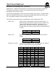
Signal Indicators The signal indicators provide information about the integrity and
robustness of the RF Signal. The three levels may be described as
a function of data throughput.
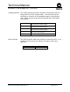
Data Loss Cause The data loss cause indicators provide information about packets
that are discarded due to throughput constraints. Two indications
are provided, Buffer Overrun and Retry Exhausted. Scanner retries
must be set at a level that mitigates data loss at the system level.
Strong Indicates the best data throughput. Data packets are
being transferred to the radio at a rate equivalent to
between 100% and 110% of full CAN trunk line loading
(at 125k baud).
Poor Reduced data throughput. Data packets are being
transferred at a rate between 50% and 100% loading at
125k baud.
Weak Radios are linked, but data throughput is low. Data
packets are being transferred at a rate between 0% to
50% loading.
No Indicators Data rate is zero. No RF link established.
Buffer Overrun CAN packets entering the transmit buffer have
overrun the RF link capacity. One or more CAN
messages are discarded.
Retry
Exhausted
The configured number of RF transmit retries
has been exceeded. One or more RF packets
are discarded. Note: RF data packets may
contain up to 2 CAN messages.
No Indicators No data loss.