
User's Manual


Technical Manual
Wireless CAN Bridge 500 (CB-500)
Matric Technical Manual 185-XXXX, V1 Page 9 of 11
INSTALLATION:
The Wireless CAN Bridge can be bolted directly to a control panel, or mounted to a DIN
rail. Remove the two decorative covers at the right and left ends of the lid to access the
mounting holes for direct panel mount (or to attach the DIN rail clips). See the
Configuration section for instruction on removing the decorative covers.
CAUTION: Many types of threadlock will weaken the plastic enclosure of the CAN
Bridge. Instead, use lock washers, or a threadlock that will not damage plastic (such as
Premabond MM115) to secure mounting screws. Also, do not over-torque panel
mounting screws. Use washers as needed to protect the enclosure and provide a solid
base for tightening mounting screws.
A DIN rail mounting kit is available for attaching the Wireless CAN Bridge to either EN
50-022 or EN 50-035 din rails. The DIN rail mounts are attached to the same holes
used for direct panel mounting.
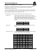
The Wireless CAN Bridge provides a sealed micro style connector that complies with
the physical standards for DeviceNet* connectors. The CB-300 requires a tap to
interface into the DeviceNet* trunk line. The pinout for the connector is shown at left.
12
43
5
Male (pins)
1 - Drain (bare)
2 - V+ (red)
3 - V- (black)
4 - CAN_H (white)
5 - CAN_L (blue)